Eureka AIR delivers breakthrough ideas for toughest innovation challenges, trusted by R&D personnel around the world.

Electric energy transmission device and electric vehicle charging system

A technology for power transmission and conductive terminals, applied in electric vehicle charging technology, electric vehicles, charging stations, etc., can solve the problems of easy overheating, low cooling efficiency, complicated manufacturing process of power wiring harness, etc., achieve easy operation and improve cooling efficiency , Improve the effect of complex manufacturing process

Pending Publication Date: 2021-07-30
JIANGLING MOTORS
View PDF0 Cites 1 Cited by
  • Summary
  • Abstract
  • Description
  • Claims
  • Application Information

AI Technical Summary

Problems solved by technology

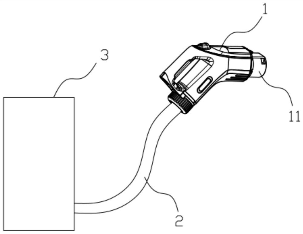
[0005] In order to solve the above technical problems, the present invention provides an electric energy transmission device, which realizes high-power electric energy transmission through the conductive liquid in the pipeline, and at the same time, the conductive liquid circulating in the pipeline is cooled by the cooling unit and can cool the conductive terminals, effectively improving current There are problems such as complex manufacturing process of power wiring harness, low cooling efficiency and easy overheating

Method used


Image

  • Electric energy transmission device and electric vehicle charging system
  • Electric energy transmission device and electric vehicle charging system
  • Electric energy transmission device and electric vehicle charging system

Examples


Embodiment Construction

[0037] Embodiments of the present invention are described in detail below, examples of which are shown in the drawings, wherein the same or similar reference numerals designate the same or similar elements or elements having the same or similar functions throughout. The embodiments described below by referring to the figures are exemplary and are intended to explain the embodiments of the present invention and should not be construed as limitations of the present invention.

[0038] In the description of the embodiments of the present invention, it should be understood that the terms "length", "width", "upper", "lower", "front", "rear", "left", "right", "vertical ", "horizontal", "top", "bottom", "inner", "outer" and other indicated orientations or positional relationships are based on the orientations or positional relationships shown in the drawings, and are only for the convenience of describing the embodiments of the present invention and simplifying Describes, but does no...


PUM


Abstract

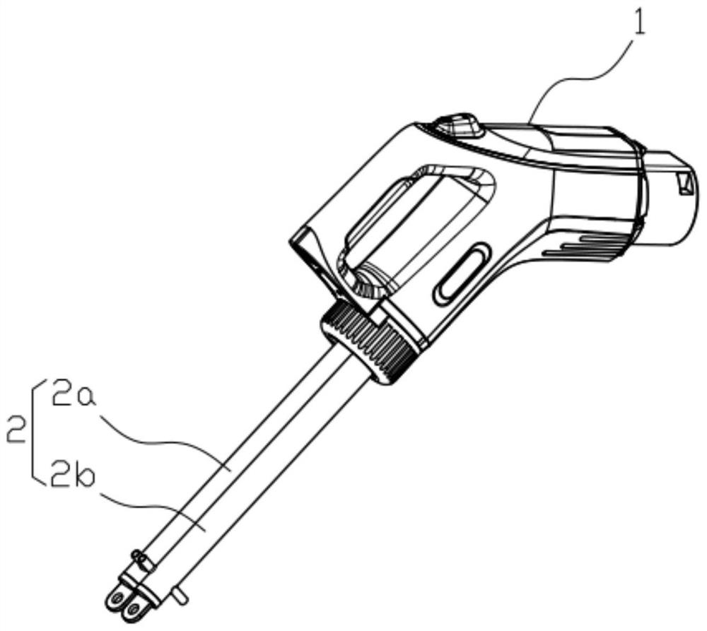
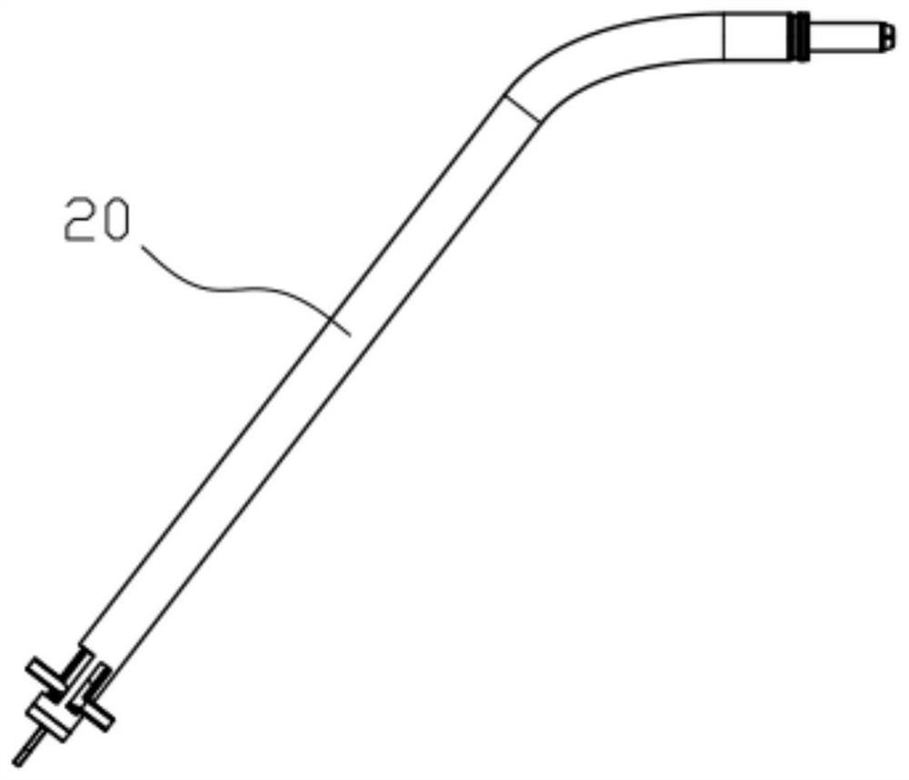
The invention provides an electric energy transmission device, and the device comprises a pipeline and a cooling unit; the pipeline comprises a pipeline, a first conductive terminal and a second conductive terminal; the first conductive terminal and the second conductive terminal are tightly assembled at the two ends of the pipeline; the cooling unit is communicated with the pipeline, the pipeline of the cooling unit and the pipeline of the pipeline form a closed annular pipeline, and conductive liquid is arranged in an inner cavity of the annular pipeline. The electric energy is transmitted in the pipeline through the conductive liquid, and the conductive liquid circularly flows in the pipeline and flows through the cooling unit to realize heat exchange, so the conductive liquid can cool the first conductive terminal and the second conductive terminal while transmitting the electric energy, the cooling efficiency is improved, and a larger current can be safely borne; and the problem of complex manufacturing process of the existing power wire harness is also improved. The invention further relates to an electric automobile charging system adopting the electric energy transmission device, high-power charging of an electric automobile is safely achieved, meanwhile, the flexibility of a charging gun cable is improved, and easy charging operation is facilitated.

Description

technical field [0001] The invention belongs to the technical field of high-power charging of electric vehicles, and in particular relates to an electric energy transmission device and an electric vehicle charging system using the electric energy transmission device. Background technique [0002] With the development of new energy vehicle technology, users have higher and higher requirements for the charging efficiency of electric vehicles, especially the network layout of charging piles on national highways, and the demand for high-power charging technology is becoming increasingly urgent. At present, the cross-section of the power transmission device (such as the power harness) of the DC charging gun has reached 70 square millimeters, which can only withstand a continuous charging current of 250A, which cannot meet the transmission needs of larger currents. In order to increase the current-carrying capacity of the charging equipment, the method of increasing the wire diame...

Claims


Application Information

Patent Timeline
Patent Type & Authority Applications(China)
IPC IPC(8): H01B7/00H01B7/42B60L53/18H01R31/06H02G3/03H02G3/04
CPCB60L53/18H01B7/0027H01B7/423H01R31/06H02G3/03H02G3/0462Y02T10/70Y02T10/7072Y02T90/14
Inventor 林金源游道亮董冰丁文敏
Owner JIANGLING MOTORS
Why Eureka
Eureka Blog
Learn More