a transformer

A technology for transformers and installation boxes, applied in the field of transformers, can solve problems such as easy occurrence of fire and inability to put out open fires in time, and achieve the effects of easy replacement and maintenance, easy disassembly, and fire avoidance.

Active Publication Date: 2021-09-24
江苏龙创电气有限公司
View PDF0 Cites 0 Cited by
  • Summary
  • Abstract
  • Description
  • Claims
  • Application Information

AI Technical Summary

Problems solved by technology

[0005] The purpose of the present invention is to solve the problem in the prior art that the fire cannot be extinguished in time, and a transformer is proposed.

Method used


Image

  • a transformer
  • a transformer
  • a transformer

Examples


Embodiment 1

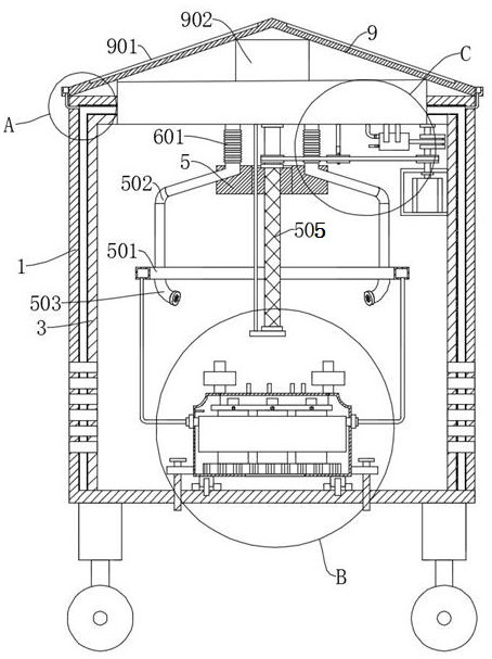
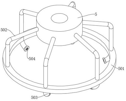
[0030] Embodiment one: refer to Figure 1-7 , a transformer, including an installation box 1, and also includes: an electrical assembly 4 detachably connected to the installation box 1, wherein the electrical assembly 4 includes a housing 401, and a heat sink 402 is arranged in the housing 401, and the heat sink 402 is fixed The winding 403 is connected, and the top of the casing 401 is provided with a terminal 404, which is electrically connected to the winding 403; the shunt box 406 fixedly connected to the inner wall of the casing 401 is used to spray dry powder to the winding 403; it is installed in the installation box 1 Divider ring 501 inside; connection block 5 arranged in installation box 1; second pipeline 502, both ends are connected with connection block 5 and distribution ring 501 respectively; dry powder box 6 fixedly connected on the top of installation box 1; fourth pipeline 601, both ends are respectively connected with the discharge end of the dry powder box ...

Embodiment 2

[0032] Embodiment two: refer to figure 1 with Image 6 , a transformer, which is basically the same as Embodiment 1, furthermore, the driving part includes a motor 7, the inner shell 3 is fixedly connected in the installation box 1, the motor 7 is fixedly connected to the inner wall of the inner shell 3, and the output end of the motor 7 The drive shaft 701 is fixedly connected, the bottom of the dry powder box 6 is rotatably connected with a reciprocating screw mandrel 505, the connecting block 5 is threaded on the reciprocating screw mandrel 505, and the reciprocating screw mandrel 505 and the drive shaft 701 are rotatably connected through the pulley transmission group 702.

[0033] Start the motor 7, the motor 7 rotates the drive shaft 701, the drive shaft 701 rotates the reciprocating screw mandrel 505 through the pulley transmission group 702, the bottom of the dry powder box 6 is fixedly connected with a guide rod, and the guide rod runs through the connecting block 5, ...

Embodiment 3

[0034] Embodiment three: refer to figure 1 with Image 6 , a transformer, basically the same as the second embodiment, the pressurized assembly includes a piston 704, the piston 704 is fixedly connected to the bottom of the dry powder box 6, the exhaust end of the piston 704 communicates with the dry powder box 6 through the air pipe 705, and the inlet of the piston 704 The air end communicates with the inside of the installation box 1 , the drive shaft 701 is fixedly connected with a crankshaft 703 , and the drive end of the piston 704 is rotatably connected with the crankshaft 703 .

[0035] The crankshaft 703 makes the piston 704 work, and the input and output ends of the piston 704 are provided with check valves. The piston 704 absorbs the air inside the installation box 1 and sends it into the dry powder box 6, increasing the pressure in the dry powder box 6, and using the pressure to make the dry powder The dry powder box 6 is ejected to spray the dry powder onto the co...


PUM


Abstract

The invention discloses a transformer and belongs to the technical field of transformers. A transformer, comprising an installation box, further comprising: an electrical assembly detachably connected to the installation box, wherein the electrical assembly includes a casing, and a heat sink is arranged in the casing, and a heat sink is fixedly connected to the heat sink. Windings, the top of the housing is provided with terminals, the terminals are electrically connected to the windings; the shunt box fixedly connected to the inner wall of the housing is used to spray dry powder to the windings; the shunt box arranged in the installation box Ring; the connecting block arranged in the installation box; the present invention automatically uses dry powder to extinguish the fire of the electrical components when they spontaneously ignite, preventing the electrical components from continuing to burn and causing a fire, and by collecting rainwater, the rainwater is used to reduce the temperature inside the installation box , so as to reduce the possibility of spontaneous combustion of electrical components, and the water in the water chamber can absorb the vibration waves generated by the electrical components, thereby reducing noise.

Description

technical field [0001] The invention relates to the technical field of transformers, in particular to a transformer. Background technique [0002] Transformer is a device that uses the principle of electromagnetic induction to change AC voltage. The main components are primary coil, secondary coil and iron core. The main functions are: voltage conversion, current conversion, impedance conversion, isolation, voltage stabilization, etc., which can be divided according to the purpose For: power transformers and special transformers, transformers can convert electrical energy into high-voltage and low-current forms, and then convert them back, thus greatly reducing the loss of electrical energy during transmission. Therefore, using transformers to convert high-voltage electrical energy enables power generation Factories can be built far away from electricity. [0003] In order to facilitate the quick installation of the transformer, a pre-installed box-type mobile transformer h...

Claims


Application Information

Patent Timeline
Patent Type & Authority Patents(China)
IPC IPC(8): H01F27/16H01F27/02H01F27/00H01F27/33A62C31/05A62C31/00A62C37/00A62C3/16
CPCA62C3/16A62C31/00A62C31/05A62C37/00H01F27/002H01F27/025H01F27/16H01F27/33
Inventor 沈宝春
Owner 江苏龙创电气有限公司
Why Eureka
Try Eureka