

Stamping device for aluminum alloy profile machining
A technology of aluminum alloy profiles and stamping devices, applied in metal processing equipment, feeding devices, positioning devices, etc., can solve problems such as hidden safety hazards and low work efficiency, and achieve the effects of avoiding crush injuries, high work efficiency, and convenient work.
- Summary
- Abstract
- Description
- Claims
- Application Information
AI Technical Summary
Problems solved by technology
Method used
Image

Examples
Embodiment 1
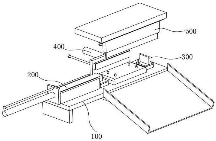
[0037] see figure 1 , the present invention provides a technical solution: a stamping device for processing aluminum alloy profiles, including a mounting assembly 100 and a feeding assembly 200, wherein the feeding assembly 200 is installed on the mounting assembly 100 to realize automatic feeding.
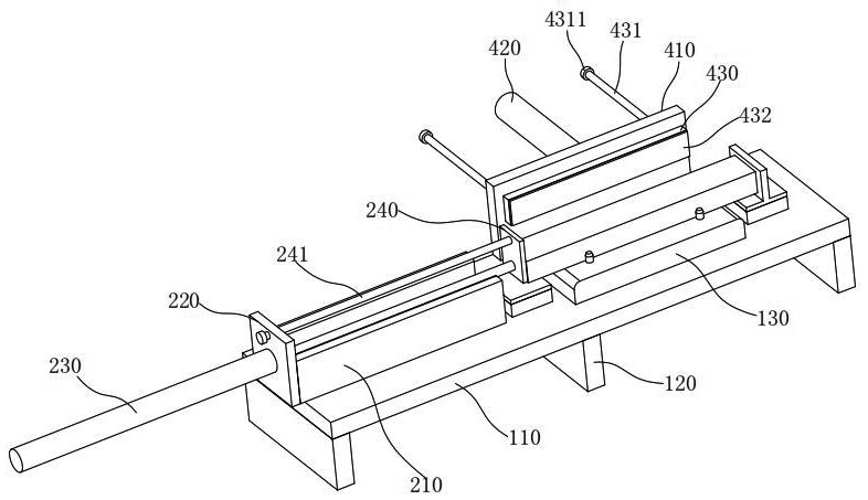
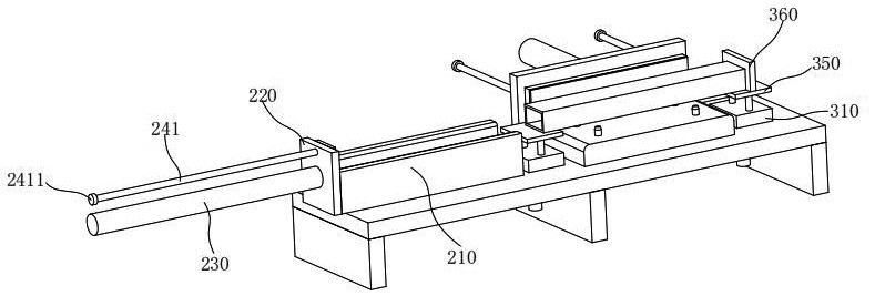
[0038] see figure 2 with Image 6 , the installation assembly 100 includes a first installation block 110, a support block 120, a lower mold 130, a second installation block 140 and an upper mold 150, and the support block 120 is fixed and installed under the first installation block 110 by bolts to support the first The function of the mounting block 110 is that the lower mold 130 is fixedly installed on the first mounting block 110 with an interference fit. It should be noted that limit pins 131 are arranged on both sides of the lower mold 130 (such Figure 5 ), the limit pin 131 is constituted by a limit profile. An upper die 150 is arranged above the lower die 130 , and th...
PUM
 Abstract
Description
Claims
Application Information