
Regeneration control method and system for vehicle particulate matter trap and storage medium

A particle trap and regeneration control technology, which is applied to the electronic control of exhaust treatment devices, machines/engines, mechanical equipment, etc., can solve the rationality of relying on regeneration control strategies, low regeneration control accuracy and efficiency, and lack of strategies. Flexibility and other issues, to achieve the effect of easy deployment, ensuring accuracy and rationality, and good flexibility

Active Publication Date: 2021-08-03
UNITED AUTOMOTIVE ELECTRONICS SYST
View PDF15 Cites 5 Cited by
  • Summary
  • Abstract
  • Description
  • Claims
  • Application Information

AI Technical Summary

Problems solved by technology

The traditional GPF regeneration control strategy, because it is impossible to know the road condition information in the future driving mileage in advance, only considers the current state of the vehicle and controls the GPF regeneration process according to the preset control rules, resulting in the following defects in this control strategy: First, it cannot Making global optimization decisions based on the road condition information of the entire journey relies heavily on the rationality of the preset regeneration control strategy; second, the strategy based on fixed rules is inflexible, triggering unnecessary ignition delay, regeneration interruption and other control strategies, resulting in The regeneration process is unstable, resulting in low regeneration control accuracy and efficiency

Method used


Image

  • Regeneration control method and system for vehicle particulate matter trap and storage medium
  • Regeneration control method and system for vehicle particulate matter trap and storage medium
  • Regeneration control method and system for vehicle particulate matter trap and storage medium

Examples


Embodiment Construction

[0071] In order to make the objects, advantages and features of the present invention, the regeneration control method, system, and storage medium of the vehicle particulate trap proposed by the present invention will be further described below with reference to the accompanying drawings. It is to be noted that the figures use a very simplified form and use non-precision ratios, only to convenient, clearly assisted in the purpose of explaining the embodiments of the present invention. It will be appreciated that the accompanying drawings of the specification do not necessarily display the specific structure of the present invention, and is used in the accompanying drawings of the specification, and the illustration of certain principles of the invention also takes a slightly simplified picture. The specific design features of the present invention disclosed herein include, for example, specific dimensions, directions, positions, and shapes to be partially determined by the particu...


PUM


Abstract

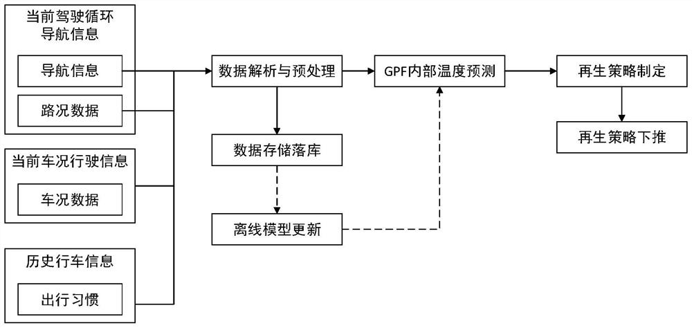
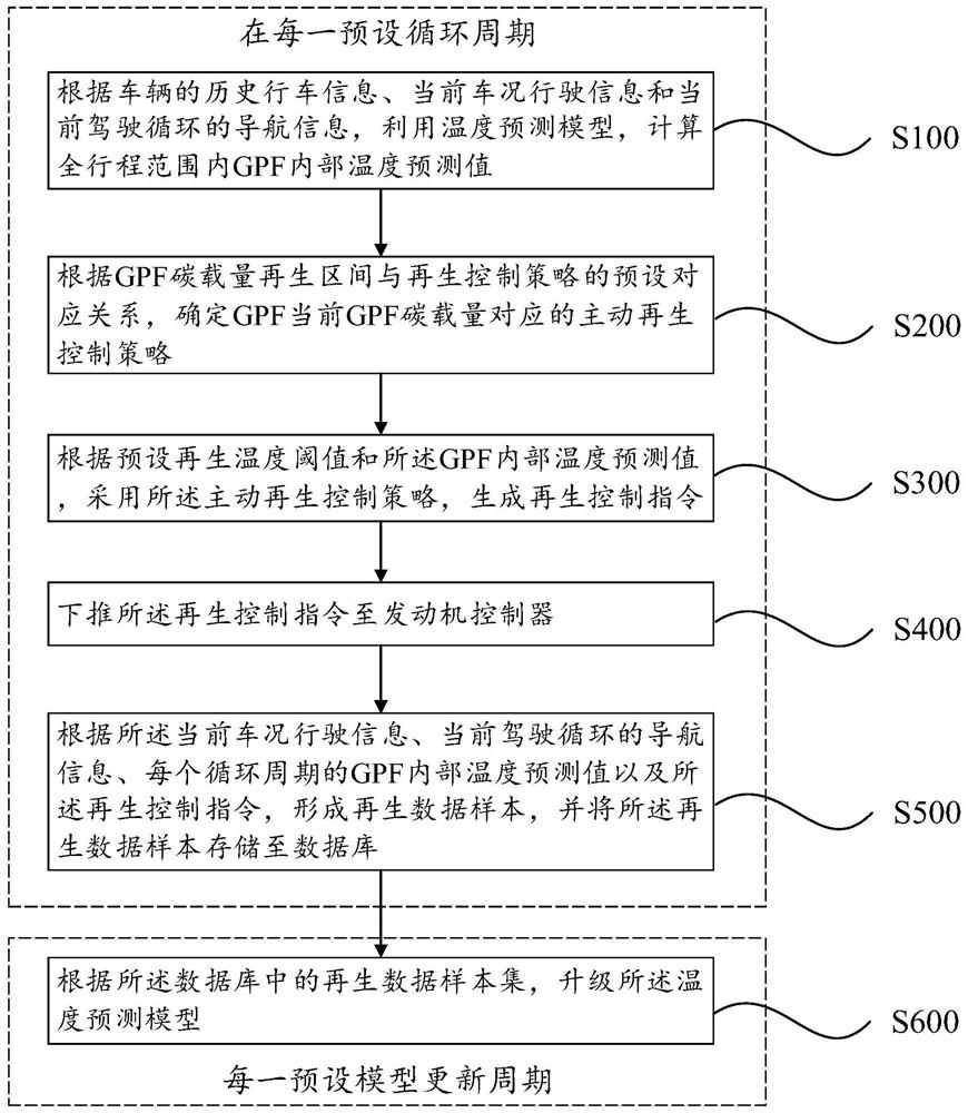
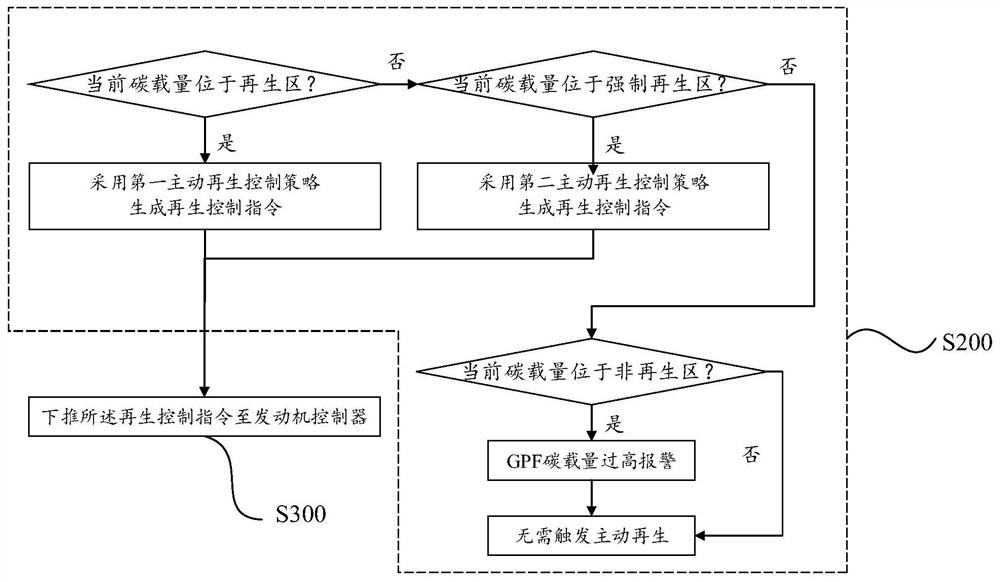
The invention provides a regeneration control method and system for a vehicle particulate matter trap and a storage medium. The regeneration control method comprises the following steps of in each preset cycle period, executing the following steps of according to historical driving information of a vehicle, current vehicle condition driving information and navigation information of a current driving cycle, utilizing a temperature prediction model to calculate a GPF internal temperature prediction value in a whole travel range; determining an active regeneration control strategy, corresponding to current GPF carbon loading capacity, of the GPF according to a preset corresponding relation between a GPF carbon loading capacity regeneration interval and a regeneration control strategy; according to a preset regeneration temperature threshold value and the GPF internal temperature predicted value, adopting the active regeneration control strategy to generate a regeneration control instruction; and pushing down the regeneration control instruction to an engine controller. According to the regeneration control method and system and the storage medium, no hardware cost needs to be increased, a GPF regeneration process can be accurately controlled, the regeneration accuracy and rationality can be remarkably improved, and the regeneration efficiency is improved.

Description

Technical field [0001] The present invention relates to the field of vehicle control technology, and more particularly to a regenerative control method, system, and storage medium of a vehicle particulate trap. Background technique [0002] "Light car pollutant emission limit and its measurement method (sixth stage)" regulations have made more stringent requirements for particulate matter in automotive emissions, and the particle quality emissions and The number of particles has increased significantly higher than the traditional PFI gasoline engine, and it has become one of the technical problems that meet the Six emissions engine needs to overcome. GPF (gasoline particles trap, Gasoline Particulate Filter) is a particulate tracing device for a gasoline engine, which is an important post-processing technique that meets emissions requirements. The GPF is a wall-flow structure, and the purpose of removing the carbon smoke by capturing the carbon nicoticle particles in the exhaust ...

Claims


Application Information

Patent Timeline
IPC IPC(8): F01N9/00
CPCF01N9/002Y02T10/40
Inventor 苏永杰徐磊吕践薛亮毛莎莎
Owner UNITED AUTOMOTIVE ELECTRONICS SYST
Learn More