
Method for detecting position of leakage point of underground concrete continuous wall

A detection method and technology of leakage point, which can solve the problem of incomplete detection of the leakage point position of the diaphragm wall by detecting the appearance of fluid at the leakage point, protection device, buoy liquid level indicator, etc., and achieve improved sealing performance, ensuring comprehensiveness, and improving accuracy

Active Publication Date: 2021-08-03
JIANGSU TESTING CENT FOR QUALITY OF CONSTR ENG
View PDF9 Cites 1 Cited by
  • Summary
  • Abstract
  • Description
  • Claims
  • Application Information

AI Technical Summary

Problems solved by technology

[0005] In order to improve the problem of incomplete detection of the leakage point position of the diaphragm wall, this application provides a detection method for the leakage point position of the underground concrete diaphragm wall

Method used


Image

  • Method for detecting position of leakage point of underground concrete continuous wall
  • Method for detecting position of leakage point of underground concrete continuous wall
  • Method for detecting position of leakage point of underground concrete continuous wall

Examples


Embodiment Construction

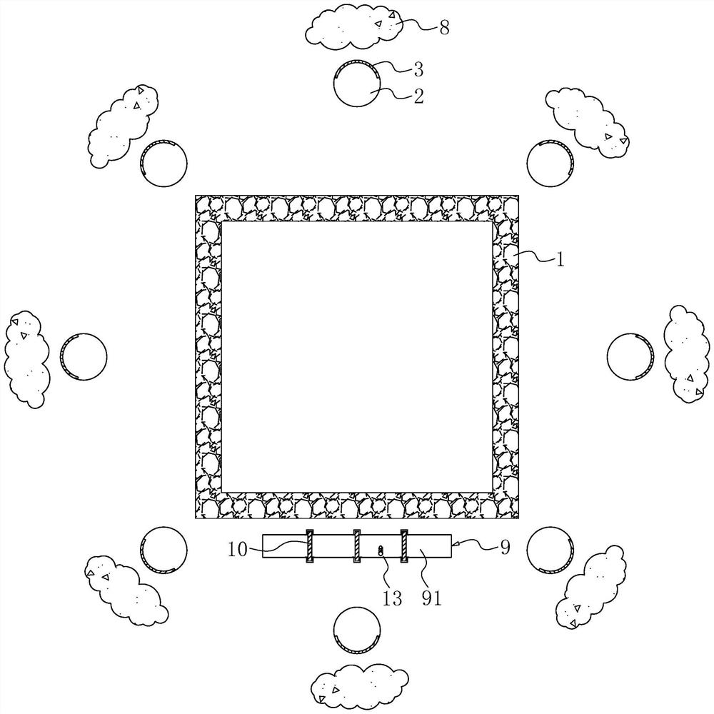
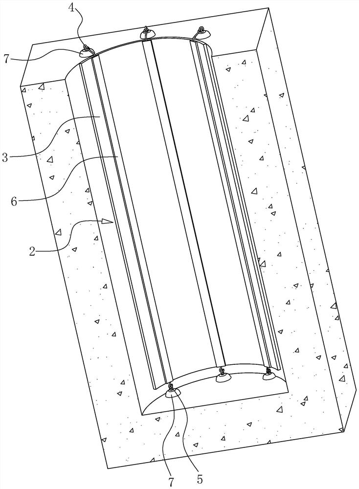
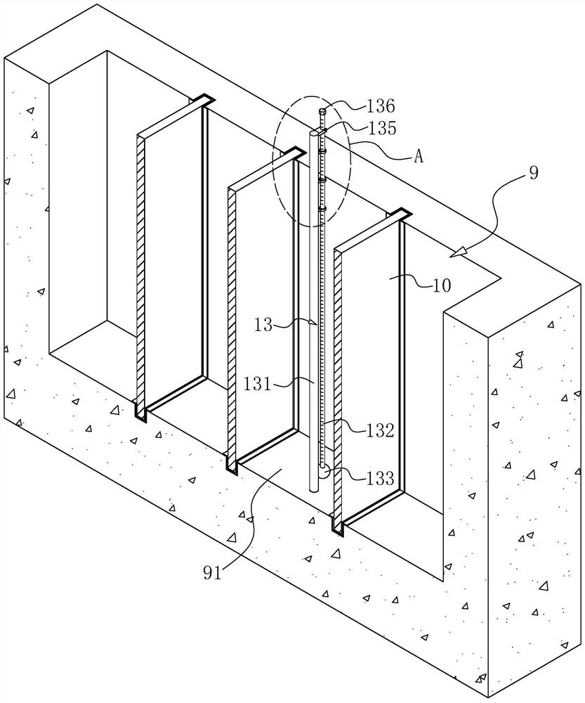
[0044] The following is attached Figure 1-4 The application is described in further detail.

[0045] The embodiment of the present application discloses a method for detecting the position of a leakage point of an underground concrete continuous wall.

[0046] refer to figure 1 , a method for detecting the location of a leak point in an underground concrete diaphragm wall, comprising the following steps:

[0047] Step S1: Dig some preliminary survey wells 2 at equal intervals on the periphery of the diaphragm wall 1, and then lay a layer of waterproof coiled material 3 on the inner wall of these preliminary survey wells 2 facing away from the diaphragm wall 1, and then lay a layer of waterproof coiled material 3 in the initial survey wells 2. Inject polyurethane 8 into the periphery of the side facing away from the diaphragm wall 1 to seal the water source for a short time, then pour water into these initial survey wells 2, and mark the highest water level;

[0048] Step S...


PUM


Abstract

The invention relates to a method for detecting the position of a leakage point of an underground concrete continuous wall. The method comprises the steps of S1, digging a preliminary exploration well out of the continuous wall; S2, extracting underground water in the continuous wall; S3, observing the water level of the preliminary exploration well, and determining that the continuous wall corresponding to the preliminary exploration well with the reduced water level is the orientation of a leakage point; S4, digging a detection groove outside the leakage point area of the continuous wall, and dividing the detection groove into a plurality of detection intervals by using partition plates; S5, filling water into the detection groove, observing the water level of each detection interval, and if the water level of a certain detection interval drops, determining that the continuous wall corresponding to the detection interval is the position of the leakage point; S6, pumping out water in the detection groove, taking out the partition plates, reserving the two partition plates on the two sides of the detection interval, and backfilling the other detection intervals; and S7, irrigating the detection interval step by step, conducting standing for a period of time after each time of irrigation, observing the water level change, and if the water level drops at a certain time, determining the position corresponding to the water level height as the final position of the leakage point. The method has the effect of improving the comprehensiveness of leakage point position detection of the continuous wall.

Description

technical field [0001] The present application relates to the field of diaphragm wall quality detection, in particular to a method for detecting the location of leakage points of underground concrete diaphragm walls. Background technique [0002] Underground concrete diaphragm wall is referred to as underground diaphragm wall or diaphragm wall. Diaphragm wall is a kind of trenching machine used on the ground in foundation engineering. Along the peripheral axis of deep excavation project, under the condition of mud retaining wall, a narrow and long groove. After clearing the tank, hang the reinforcement cage in the tank, and use the conduit method to fill the underwater concrete to form a unit tank section. This is done section by section, and a continuous reinforced concrete wall is built underground as a water interception, anti-seepage, load-bearing, and water-retaining structure. [0003] After the construction of the diaphragm wall is completed, in order to ensure the ...

Claims


Application Information

Patent Timeline
Patent Type & Authority Applications(China)
IPC IPC(8): G01M3/04G01F23/58E02D31/02E02D31/10
CPCG01M3/04G01F23/58E02D31/02E02D31/10
Inventor 崇金玲
Owner JIANGSU TESTING CENT FOR QUALITY OF CONSTR ENG
Learn More