Supercharge Your Innovation With Domain-Expert AI Agents!

A magnetic tile used for a motor, a motor rotor, and a motor

A technology for motor rotors and magnetic tiles, which is applied in the field of motors, magnetic tiles, and motor rotors. It can solve the problems of large axial magnetic pull and achieve the effects of low production cost, simple structure, and improved performance ratio.

Active Publication Date: 2022-05-27
GREE ELECTRIC APPLIANCES INC +1
View PDF13 Cites 0 Cited by
  • Summary
  • Abstract
  • Description
  • Claims
  • Application Information

AI Technical Summary

Problems solved by technology

[0004] In view of this, the present invention discloses a magnetic tile for a motor, a motor rotor, and a motor to at least solve the problem that the motor rotor is subject to a relatively large axial magnetic pull

Method used


Image

  • A magnetic tile used for a motor, a motor rotor, and a motor
  • A magnetic tile used for a motor, a motor rotor, and a motor
  • A magnetic tile used for a motor, a motor rotor, and a motor

Examples


Embodiment 1

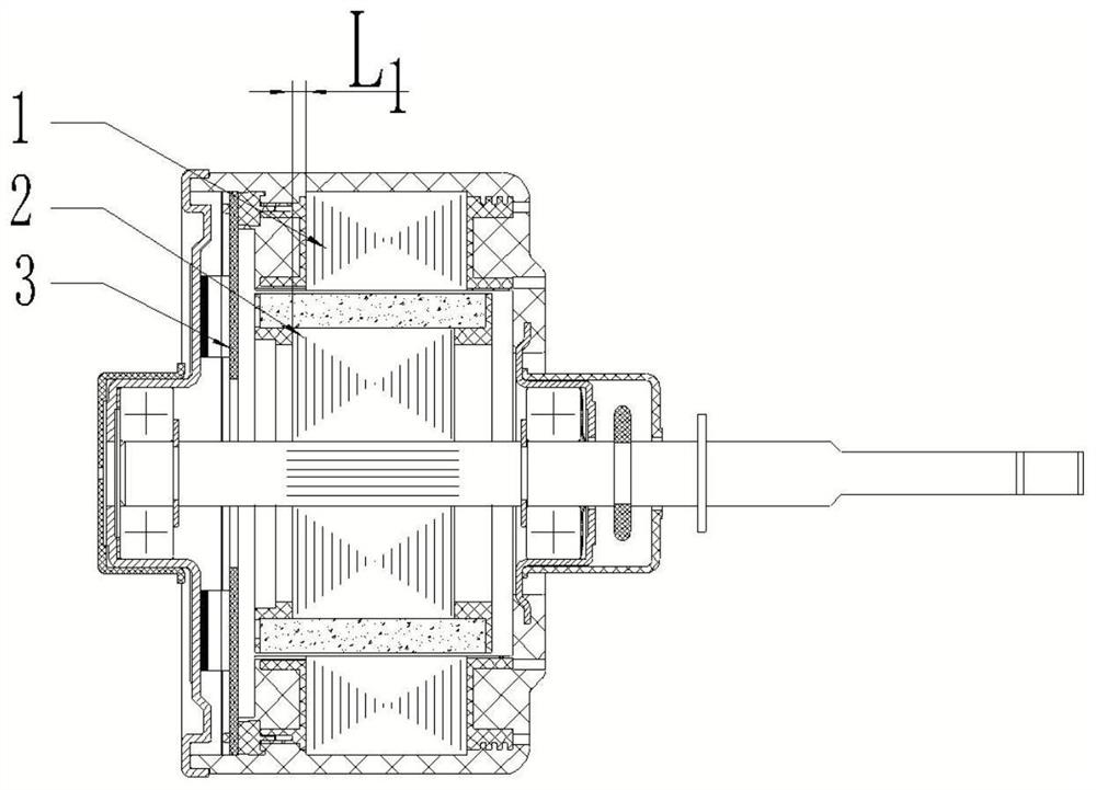
[0051] In this embodiment, a magnetic shoe for a motor is provided, which is used for a permanent magnet motor in which the rotor iron core and the stator iron core are dislocated along the rotor axis. The motor includes a motor rotor and a stator, and the magnetic tile includes:

[0052] The excitation part is covered on the outer peripheral surface of the rotor iron core, and cooperates with the stator air gap to form an excitation circuit;

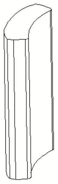
[0053] The dislocation portion is formed on the first end face of the excitation portion, and the end side dislocation portion protrudes from the end face of the stator iron core and the end face of the rotor iron core on the same side to form a dislocation arrangement with the stator iron core and the rotor iron core, The dislocation part includes: an induction part for being induced by the rotor position induction element of the motor; and a magnetic bridge for connecting the induction part and the excitation part to stagger the induc...

Embodiment 2

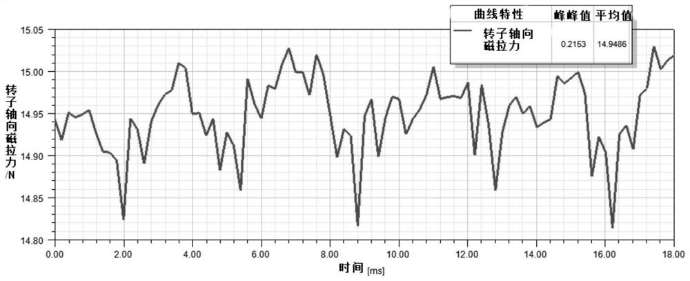
[0063] In this embodiment, a motor rotor is provided, and the motor rotor includes: a rotor; and a plurality of magnetic tiles that are molded outside the rotor, and any one of the above magnetic tiles is used for the magnetic tiles. That is, any one of the above-mentioned "Z" type, "return" type or "I" type permanent magnet structure (magnetic tile) is enclosed into a circle to enclose the rotor. It should be noted that the proportion of each magnetic tile is determined according to the actual magnetic pole scheme (that is, the proportion of each magnetic tile is determined according to the actual magnetic pole 8P, 10P... scheme of the motor); this kind of After the structure realizes the dislocation of the stator and rotor cores, the permanent magnet structure of the present invention greatly reduces the axial magnetic pulling force compared with the existing permanent magnet structure, and the effect is obvious. The noise is improved and the service life of the motor is inc...

Embodiment 3

[0065] In this embodiment, a motor is provided, and the motor includes the above-mentioned motor rotor or magnetic tile. Since the stator and rotor of the motor are placed asymmetrically, the permanent magnets of the motor rotor in this embodiment are of "Z" type, "return" type or "I" type structure. It greatly reduces the magnitude of the axial magnetic pull, and solves the problem that the axial magnetic pull of the motor rotor causes the bearing and the wave pad to be under force for a long time, and the performance and life of the motor are seriously affected.

[0066] The permanent magnet of the present invention adopts the "Z" type, "return" type or "I" type structure, and the outer contour of the asymmetric part of the permanent magnet relative to the stator core and the excitation part of the air gap adopts the same three-segment arc The structure solves the problem of excessive motor torque and magnetic pull pulsation.


PUM


Abstract

The invention discloses a magnetic tile, which is used for a permanent magnet motor in which the rotor iron core and the stator iron core are dislocated along the rotor axial direction. The stator air gap fits to form an excitation circuit; the dislocation part is formed on the first end surface of the excitation part, and the dislocation part protrudes from the end surface of the stator core and the end surface of the rotor core on the same side to be compatible with the stator core. . The rotor core is arranged in a dislocation; the dislocation part includes: an induction part, used for being induced by a rotor position induction element of the motor; and a magnetic bridge, used for connecting the induction part and the excitation part.

Description

technical field [0001] The present invention relates to the technical field of motors, and in particular, to a magnetic tile for a motor, a rotor of the motor, and a motor. Background technique [0002] At present, with the development of motor technology, the current motor has an iron-shell structure and a plastic-encapsulated structure. Among them, the built-in inductive control motor cannot sense the rotor position due to the insufficient distance between the rotor position sensing element and the surface-mounted permanent magnet. It is often necessary to dislocate the rotor and the stator, such as figure 1 As shown, the dislocation distance between the stator 1 and the rotor 2 is L1 (depending on the actual situation), so that the distance between the permanent magnet on the rotor and the position sensing element 3 on the control board is satisfied; at the same time, after the asymmetric placement, the height of the permanent magnet needs to be It is higher than the sta...

Claims


Application Information

Patent Timeline
Patent Type & Authority Patents(China)
IPC IPC(8): H02K1/274H01F7/02
CPCH02K1/274H01F7/021H02K2201/06H02K2213/03
Inventor 李刚纪泽轩郭一星丁佳婷刘丽刚毛鑫
Owner GREE ELECTRIC APPLIANCES INC
Features
  • R&D
  • Intellectual Property
  • Life Sciences
  • Materials
  • Tech Scout
  • Unparalleled Data Quality
  • Higher Quality Content
  • 60% Fewer Hallucinations
Learn More