
Heat dissipation device

A heat dissipation device and heat dissipation plate technology, which is applied in the direction of cooling/ventilation/heating transformation, electrical components, electrical equipment structural parts, etc., can solve the problems of low heat dissipation efficiency of heat dissipation devices, large local resistance loss, etc., and reduce resistance loss , Increase the heat exchange area and avoid the effect of structural loss

Pending Publication Date: 2021-08-03
SHENZHEN SILVER BASIS TECH
View PDF0 Cites 0 Cited by
  • Summary
  • Abstract
  • Description
  • Claims
  • Application Information

AI Technical Summary

Problems solved by technology

[0005] The purpose of the embodiments of the present application is to provide a heat sink, aiming to solve the technical problems of low heat dissipation efficiency and large local resistance loss in the prior art

Method used


Image

  • Heat dissipation device
  • Heat dissipation device
  • Heat dissipation device

Examples


Embodiment Construction

[0024] In order to make the technical problems, technical solutions and beneficial effects to be solved by the present application clearer, the present application will be further described in detail below in conjunction with the accompanying drawings and embodiments. It should be understood that the specific embodiments described here are only used to explain the present application, and are not intended to limit the present application.

[0025] It should be noted that when an element is referred to as being “fixed” or “disposed on” another element, it may be directly on the other element or be indirectly on the other element. When an element is referred to as being "connected to" another element, it can be directly connected to the other element or indirectly connected to the other element. In the case of no conflict, the embodiments in the present application and the features in the embodiments can be combined with each other. The present application will be described in ...


PUM


Abstract

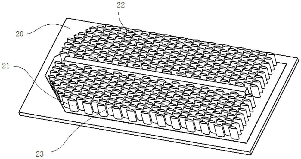
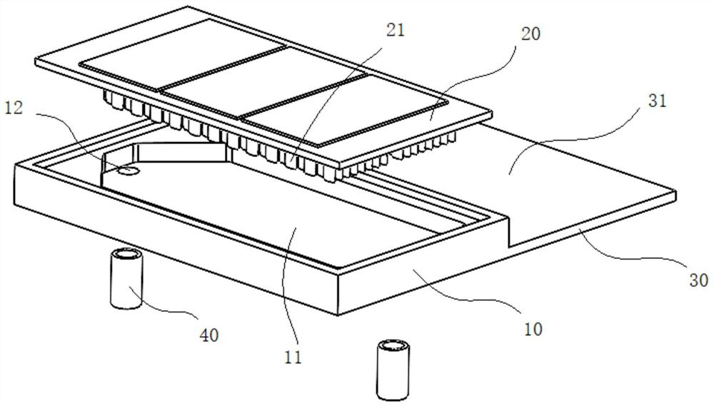
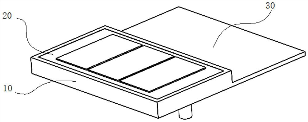
The invention is suitable for the technical field of new energy heat dissipation equipment, and provides a heat dissipation device which comprises: a heat dissipation body, wherein a liquid containing groove is formed in the heat dissipation body, a first through hole is formed in the first end of the liquid containing groove, and a second through hole is formed in the second end of the liquid containing groove; and a first heat dissipation plate which is arranged on the liquid containing groove in a covering mode so as to form a liquid containing cavity. A plurality of fins are arranged at the bottom of the first heat dissipation plate, first fluid resistance reduction faces are arranged at the first ends of the fins, second fluid resistance reduction faces are arranged at the second ends of the fins, the first fluid resistance reduction faces face the first ends of the liquid containing grooves, and the second fluid resistance reduction faces face the second ends of the liquid containing grooves. Therefore, resistance loss and liquid pressure loss are reduced, structural loss is avoided, reversible design of the inflow hole and the outflow hole can be achieved by arranging the fluid resistance reduction faces at the two ends, and various working condition changes can be effectively coped with.

Description

technical field [0001] This application belongs to the technical field of new energy heat dissipation equipment, and more specifically relates to a heat dissipation device. Background technique [0002] From a global perspective, new energy vehicles are recognized as the mainstream of the future automotive industry, and many countries are actively developing and guiding new energy vehicles. With the development of new energy vehicles, electric drive and electronic control batteries, as the three core technologies of new energy vehicles, have also attracted much attention. [0003] The electric control and electric drive system is composed of many power electronic converters and corresponding controllers. The solid-state devices transfer a large amount of power energy to the input end of the motor. The heat loss of the electric devices must be dissipated in time to ensure the safety of the overall vehicle system. Therefore, the efficient heat dissipation design of the suppor...

Claims


Application Information

Patent Timeline
Patent Type & Authority Applications(China)
IPC IPC(8): H05K7/20
CPCH05K7/20218H05K7/20236H05K7/20272H05K7/20418
Inventor 胡作寰张传美耿丽丽
Owner SHENZHEN SILVER BASIS TECH
Learn More