Knee joint cavity positioning device for stem cell injection and preparation method thereof

A positioning device and knee joint technology, applied in the field of medical equipment, can solve problems such as inconvenient operation, and achieve the effects of convenient operation, accurate positioning of injection, and avoiding deviation

Pending Publication Date: 2021-08-06
NANJING DRUM TOWER HOSPITAL
View PDF0 Cites 0 Cited by
  • Summary
  • Abstract
  • Description
  • Claims
  • Application Information

AI Technical Summary

Problems solved by technology

[0006] It can be seen that these three patents are all used to adjust the bending degree of the patient's knee joint and fix it, which is convenient for the doctor to inject, but whether the injection is accurate or not depends on the doctor's experience, and the operation is inconvenient

Method used


Image

  • Knee joint cavity positioning device for stem cell injection and preparation method thereof
  • Knee joint cavity positioning device for stem cell injection and preparation method thereof
  • Knee joint cavity positioning device for stem cell injection and preparation method thereof

Examples


Embodiment 1

[0035] A method for preparing a knee joint cavity positioning device for stem cell injection, comprising the steps of:

[0036] Step 1): Ask the patient to lie on his back and straighten the knee joint, and first use imaging examination to obtain a preliminary three-dimensional model of the knee joint, including bones and the shape of the knee joint body surface; then combine the three-dimensional scanner to obtain an accurate three-dimensional model of the knee joint body surface shape, Use mimics software to fit the space coordinates of the two 3D models to obtain the final 3D model of the knee joint;

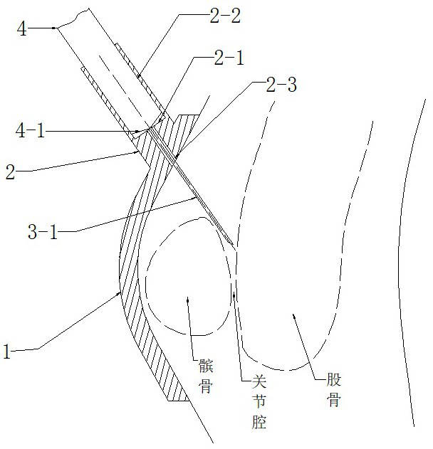
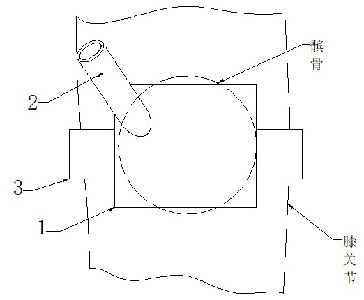
[0037] Step 2): Import the final three-dimensional model of the knee joint into 3-matic software to design the knee joint profiling part 1, the bottom surface of the knee joint profiling part 1 is consistent with and fits the shape of the area directly in front of the knee joint;

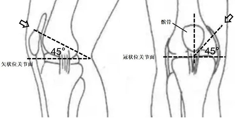
[0038] Step 3): Preliminarily confirm the needle insertion angle and the needle insertion posit...

Embodiment 2

[0053] A method for preparing a knee joint cavity positioning device for stem cell injection, comprising the steps of:

[0054] Step 1): Ask the patient to lie on his back and straighten the knee joint, and first use imaging examination to obtain a preliminary three-dimensional model of the knee joint, including bones and the shape of the knee joint body surface; then combine the three-dimensional scanner to obtain an accurate three-dimensional model of the knee joint body surface shape, Use mimics software to fit the space coordinates of the two 3D models to obtain the final 3D model of the knee joint;

[0055] Step 2): Import the final three-dimensional model of the knee joint into 3-matic software to design the knee joint profiling part 1, the bottom surface of the knee joint profiling part 1 is consistent with and fits the shape of the area directly in front of the knee joint;

[0056] Step 3): Preliminarily confirm the needle insertion angle and the needle insertion posit...


PUM


Abstract

The invention discloses a knee joint cavity positioning device for stem cell injection and a preparation method thereof. The knee joint cavity positioning device for stem cell injection comprises a knee joint profiling component; a positioning sleeve and a locking belt are fixedly arranged on the knee joint profiling component; the inner diameter of a positioning hole of the positioning sleeve is consistent with the outer diameter of an injector; a limiting table is arranged in the positioning sleeve; the limiting table is located at the joint of the positioning sleeve and the knee joint profiling component; the knee joint profiling component and the limiting table are provided with a through hole of which the diameter is greater than that of an injector needle at the center line of the positioning sleeve; and an inclination angle is formed between the positioning sleeve and the knee joint profiling component, and the center line of the positioning sleeve extends to a joint cavity between a patella and a femur. The knee joint cavity positioning device is simple in structure, easy to operate and capable of accurately conducting positioning injection and avoiding repeated injection.

Description

technical field [0001] The invention relates to the technical field of medical devices, in particular to a knee joint cavity positioning device for stem cell injection and a preparation method thereof. Background technique [0002] The current patents related to knee joint cavity puncture mainly focus on the adjustment and fixation of the knee joint angle to ensure the size of the medial or lateral joint space of the patellar ligament to facilitate injection, but the success rate of injection still depends on the experience of the doctor. And the prior art does not relate to the way of locating the injection point on the surface of the knee joint. [0003] Patent No. 2019209305893, the patent name is knee joint injection positioning device, which mainly solves the problem of adjusting the bending angle between the thigh and calf before performing joint injection of the knee joint. By adjusting the bending angle between the thigh and the calf, the size of the medial or later...

Claims


Application Information

Patent Timeline
Patent Type & Authority Applications(China)
IPC IPC(8): A61B90/10A61M5/42
CPCA61M5/427A61B90/10
Inventor 蒋青
Owner NANJING DRUM TOWER HOSPITAL
Why Eureka
Try Eureka