Discharging mechanism of automatic mechanical equipment

A technology of mechanical equipment and rotating mechanism, which is applied in the direction of feed, mixers, mixer accessories, etc., can solve the problems of inconvenient mixing ratio and low mixing efficiency of feed mixers, achieve good mixing effect, improve mixing efficiency, and improve mixing ratio Control the exact effect

Pending Publication Date: 2021-08-06
HUZHOU TEACHERS COLLEGE
2 Cites 0 Cited by

AI-Extracted Technical Summary

Problems solved by technology

[0004] Aiming at the technical problems existing in the prior art, the present invention provides a feeding mechanism for automatic me...

Abstract

The invention relates to the technical field of feed processing, in particular to a discharging mechanism of automatic mechanical equipment. A discharging mechanism of automatic mechanical equipment comprises a bottom plate, supporting legs are fixedly connected to the upper side wall of the bottom plate, a stirring barrel is fixedly connected to the upper ends of the supporting legs, a discharging pipe is arranged at the bottom of the stirring barrel, and a first electromagnetic valve is arranged on the side wall of the discharging pipe; and a stirring mechanism used for stirring feed is arranged in the stirring barrel, a rotating mechanism is arranged at the upper end of the stirring barrel, and a rotating disc is connected to the rotating mechanism. Compared with the prior art, the discharging mechanism of the automatic mechanical equipment has the beneficial effects that the discharging mechanism of the automatic mechanical equipment can adjust the proportion of various feeds according to requirements, so that the proportion control is more accurate and convenient, and the feeds entering the stirring barrel can be dispersed and preliminarily mixed in the rotating process of the rotating disc, so that the stirring and mixing efficiency of the feeds is improved, and the mixing and stirring effects are better.

Application Domain

Technology Topic

Image

  • Discharging mechanism of automatic mechanical equipment
  • Discharging mechanism of automatic mechanical equipment
  • Discharging mechanism of automatic mechanical equipment

Examples

  • Experimental program(1)

Example Embodiment

[0031] The principles and features of the present invention will be described below with reference to the accompanying drawings, and the exemplary examples are intended to be construed as they are intended to limit the scope of the invention.
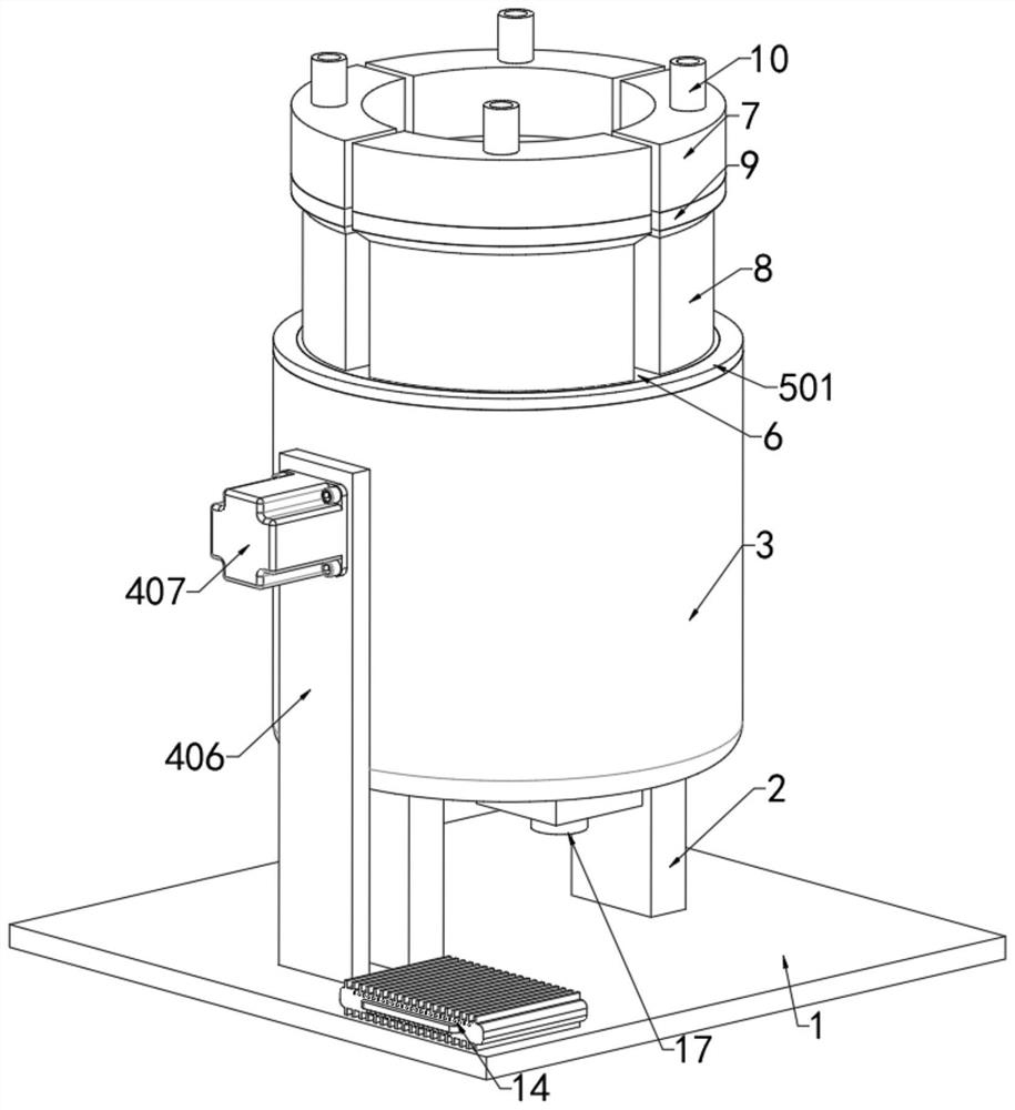
[0032] During the feeding of poultry and livestock, the preparation of feed is very important. The feed contained in the feed is a variety of feeds, which requires mixing and stirring a plurality of feeds using a mixer. At present, the mixer of stirring feed is divided into vertical and horizontal.
[0033] The inventors have been in-depth investigation and research on the feed mixing process: the mixer requires the user to add a variety of feed in a mixing bar before stirring, but the ratio is not convenient for control and adjustment during the actual operation. There is an error such that the mixing stir effect is poor, and such a discharge method such that the feed stack is placed together, so that the agitation efficiency is low.
[0034] The above problems have not been reported in the art, and the inventors have discovered the above problems and designed the technical solution.
[0035] The present invention provides the following preferred embodiments
[0036] like Figure 1-6 As shown, the discharge mechanism of an automated mechanical device includes a bottom plate 1, a bottom plate 1, and a leg 2, the upper end of the leg 2 is fixedly connected, and the bottom portion of the mixing tank 3 is provided. The tube 17, and the side wall of the discharge tube 17 is provided with a first solenoid valve 18, and the inner portion of the stirring tub 3 is provided with a stirring mechanism for stirring the feed, and the upper end of the stirring tub 3 is provided with a rotating mechanism and a rotating mechanism. There is a turning plate 6, and the upper side wall of the rotary disk 6 is provided with a plurality of arrays set of arc grooves 8, and the bottom of the respective arc grooves 8 is opened with an arc-shaped supply port 12, and the supply port 12 runs through The sidewall of the rotating disk 6 is provided, and the bottom portion of the rotary disk 6 is provided with a plurality of inclined power plates 13, and the power plate 13 is located directly below the supply port 12, and the upper end of the respective arc grooves 8 is fixedly connected to the silo 7. And the silo 7 and the curved material groove 8 are provided with a second solenoid valve 9, and the top of the respective silo 7 is provided with a discharge tube 10, and a variety of feed ratios can be adjusted according to the demand, so that the ratio control is more accurate. , Convenient, and, it is possible to make the feed into the stirring bowl 3 to dissipate and preliminate during the rotation of the rotary disc 6, thereby increasing the feed stirring mixing efficiency, and makes the mixed stirring effect better.
[0037] In this embodiment, if figure 2 and image 3 As shown, the stirring mechanism includes a stirring shaft 401 that is rotatably coupled to the bottom of the stirring tub 3, and the side wall of the agitating shaft 401 is fixedly coupled with a plurality of arrays provided with stirring blades 402, and the upper end of the agitating shaft 401 is fixedly connected to the driven bevel gear 403. The sidewall of the stirring tub 3 is rotated by the rotating shaft 405, and the active cone gear 404 is engaged with the driven bevel gear 403, and the upper wall of the bottom plate 1 is fixedly connected to the support plate 406, the side of the support plate 406. The wall is fixedly connected to the motor 407, and the output terminal of the motor 407 penetrates the side wall of the stirring tub 3 and is fixed to one end of the rotary shaft 405, the rotation of the motor 407 drives the rotation of the shaft 405 and the active cone 404, and drives the slave cone gear 403. The rotation of the stirring blade 402 is rapidly stirred to feed feed into the stirring tub 3.
[0038] In this embodiment, if figure 2 and Figure 5As shown, the rotating mechanism includes a fixing ring 501 fixed to the upper end of the stirring tub 3, and the inner side wall of the fixed ring 501 is fixedly connected to the annular disposed guide rail 502, and the side wall of the rotary disk 6 opens a ring-shaped slide 503, and sliding The slot 503 slides on the guide rail 502 to ensure that the rotary disc 6 can be rotated along the inner side wall of the fixed ring 501.
[0039] In this embodiment, if Figure 4 and Figure 5 As shown, the arcuate groove 8 is provided with a conductive groove 11, and the conductive groove 11 is provided in a drain shape, which is convenient for the feed bunker 7 into the curved tank 8, and, It is possible to accelerate feed in the curved material tank 8.
[0040] In this embodiment, if Figure 5 and Image 6 As shown, the inner side wall of the stirring tub 3 is fixedly coupled with a plurality of fixed blocks 15, and the sidewalls of the fixing block 15 are fixedly connected to the fixing rod 16, and the fixing rod 16 is located between the two power plates 13, when passing through the supply port 12 When the feed is tie, the impact is in the power plate 13, and when the rotation disk 6 is rotated, the power plate 13 is rotated, so that the side wall of the power plate 13 and the fixed bar 16 Arruntarily, and causes the power plate 13 to extrud the deformation, so that the sheet tie feed is crushed, so that the mixed stirring effect is better.
[0041] In this embodiment, if Figure 4 As shown, the inner wall of the silo 7 and the curved material tank 8 is provided with a smooth film to avoid the feed adherent thereto onto its side wall.
[0042] In this embodiment, if Figure 1-3 As shown, the upper side wall of the bottom plate 1 is provided with a controller 14, the first solenoid valve 18, the second solenoid valve 9, and the motor 407 are electrically connected to the controller 14, which is convenient for the first solenoid valve 18, a second solenoid valve. 9 and motor 407 for unified control.
[0043] The specific operation of the present invention is as follows:
[0044] First, the feed required to be mixed is stored in the silo 7 by the discharge tube 10; when mixing is required, the second solenoid valve 9 is opened by the controller 14, and various feeds are controlled by the controller 14. After the ratio, the second solenoid valve 9 is opened, the feed in the silo 7 passes through the curved material tank 8 and stirred into the stirring tub 3 through the supply port 12, so that the feed is stirred more convenient, and can be adjusted according to requirements Feed ratio, make the ratio control more accurate, convenient, so that the mixing agitation effect is better;
[0045] At the same time, when the mixed feed is entered into the stirring tub 3 through the feed port 12, the surface of the power plate 13 is impulted, and since the tilt setting of the power plate 13 is provided, the rotating disk 6 is in the gravity of the feed along the fixed ring 501. The sidewalls are rotated, so that the feedstock and preliminary mixing of the feed port 12 into the stirring tub 3 is performed during the rotation of the rotary disc 6, thereby increasing the feed stirring mixing efficiency, and makes the mixing stirring effect;
[0046] Further, when the sheet is presented by the feed of the feed port 12, the impact is between the two power plates 13 after the power plate 13, and when the rotational disk 6 is rotated, the power plate 13 is rotated, thereby so that the power plate The sidewall of 13 is abuting with the fixing rod 16 and causes the power plate 13 to extrusion, thereby extruding the plate tubular feed so that the mixing stir effect is better;
[0047] Next, the second solenoid valve 9 is turned off, and the motor 407, the rotation of the motor 407 drives the rotation of the shaft 405 and the active cone 404, thereby driving the rotation of the driven bevel gear 403 and the stirring blade 402, thereby enters the stirring barrel 3 Feed for rapid mixing;
[0048] After the mixing is completed, the motor 407 is turned off, and the first solenoid valve 18 is opened, the feed after stirring is discharged by the discharge tube 17.
[0049] In summary: The beneficial effects of the present invention are specifically reflected in the adjustment of a variety of feed ratios according to the requirements, so that the ratio control is more accurate, convenient, and, it is possible to make the feed of the feed in the stirring bar in the rotational disk 6 Disperse and preliminary mixing is made, thereby increasing feed stirring mixing efficiency, and makes mixing mixing effects better.
[0050] The preferred embodiments of the present invention are not intended to limit the invention, and any modifications, equivalents, improvements, and the like, which may be contained in the present invention. Within the range.

PUM

no PUM

Description & Claims & Application Information

We can also present the details of the Description, Claims and Application information to help users get a comprehensive understanding of the technical details of the patent, such as background art, summary of invention, brief description of drawings, description of embodiments, and other original content. On the other hand, users can also determine the specific scope of protection of the technology through the list of claims; as well as understand the changes in the life cycle of the technology with the presentation of the patent timeline. Login to view more.

Similar technology patents

Classification and recommendation of technical efficacy words

Why Eureka
Try Eureka