Automatic numerical control machining center machine tool

A technology of machining centers and machine tools, which is applied in metal processing and other directions, can solve the problems of inability to realize continuous switching of loading and unloading, inconvenient automatic positioning and fixing of products, and increased operation difficulty, so as to facilitate assembly line production, reduce processing costs, and reduce conveying equipment Effect

Active Publication Date: 2021-08-06
福建省正丰数控科技有限公司
View PDF12 Cites 2 Cited by
  • Summary
  • Abstract
  • Description
  • Claims
  • Application Information

AI Technical Summary

Problems solved by technology

[0004] In the process of automatic loading and unloading of the CNC machining center machine tools in the prior art, it is not convenient to automatically position and fix the product. It needs to be actively positioned and fixed by the gripper, and the loading and unloading are relatively independent during the loading and unloading process. Realizing the continuous switching of loading and unloading requires the staff to carry out too much control processing, which increases the difficulty of operation and reduces the processing efficiency. In view of this, we propose an automatic CNC machining center machine tool

Method used


Image

  • Automatic numerical control machining center machine tool
  • Automatic numerical control machining center machine tool
  • Automatic numerical control machining center machine tool

Examples


Embodiment Construction

[0034] The following description serves to disclose the present invention to enable those skilled in the art to carry out the present invention. The preferred embodiments described below are only examples, and those skilled in the art can devise other obvious variations.

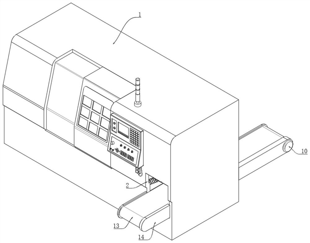
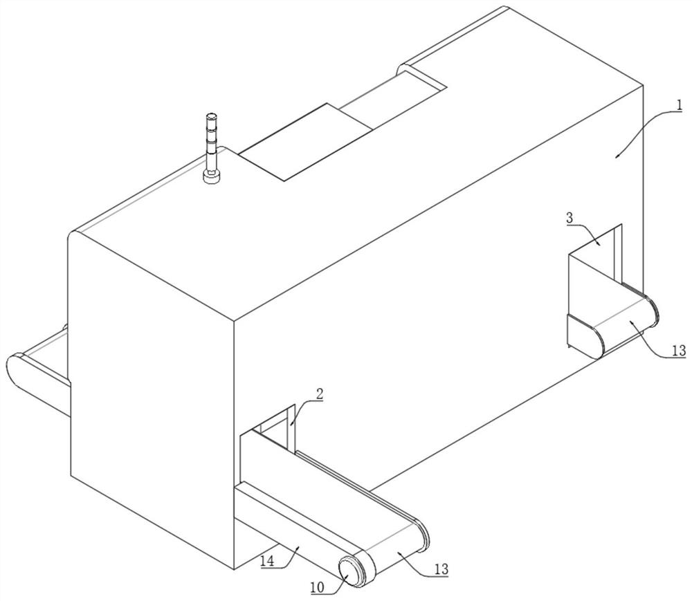
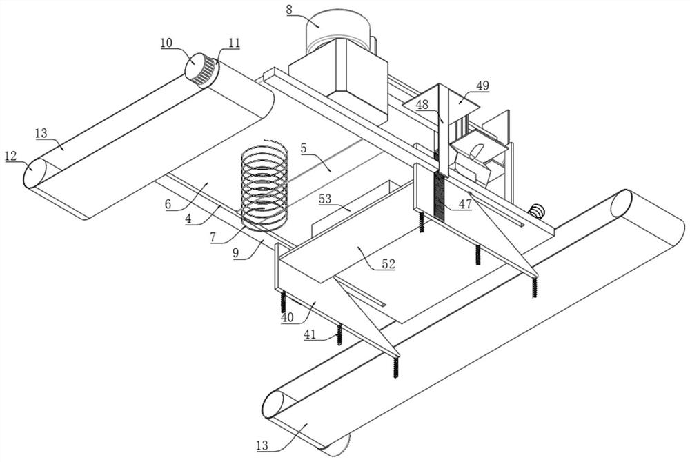
[0035] Such as Figure 1-15The shown automatic numerical control machining center machine tool includes a shell 1, and the back of the shell 1 is respectively provided with a discharge chute 2 and a feed chute 3, and the inside of the feed chute 3 and the discharge trough 2 are provided with a mechanism for conveying workpieces. Belt conveying mechanism; a support plate 9 is fixed on the inner wall of the housing 1, and a strip-shaped through hole 4 is provided on the top surface of the support plate 9 near the position of the discharge chute 2, and the inner wall of the strip-shaped through hole 4 is connected with a tool for positioning the workpiece Clamping and positioning mechanism, the numerical contr...


PUM


Abstract

The invention relates to the technical field of numerical control machining, in particular to an automatic numerical control machining center machine tool. The automatic numerical control machining center machine tool comprises a shell, a discharging groove and a feeding groove are formed in the back face of the shell, belt conveying mechanisms used for conveying workpieces are arranged inside the feeding groove and the discharging groove correspondingly, a supporting plate is fixed to the inner wall of the shell, a strip-shaped through hole is formed in the position, close to the discharging groove position, of the top face of the supporting plate, a clamping and positioning mechanism used for positioning the workpieces is connected to the inner wall of the strip-shaped through hole, numerical control machining equipment used for machining the workpieces is arranged on the supporting plate, a feeding area and a clamping area are arranged on the side, close to the feeding groove, of the supporting plate, the clamping area is close to the side of the feeding groove, the feeding area is adjacent to the clamping area, a clamping and conveying mechanism used for clamping and conveying the workpieces from the clamping area to the feeding area is arranged on the supporting plate, a pushing mechanism used for pushing the workpieces to the clamping and positioning mechanism is arranged in the feeding area, and the device is favorable for reducing the machining cost and improving the machining efficiency.

Description

technical field [0001] The invention relates to the field of numerical control machining, in particular to an automatic numerical control machining center machine tool. Background technique [0002] CNC machining centers are developed from CNC milling machines. The biggest difference from the CNC milling machine is that the machining center has the ability to automatically exchange machining tools. By installing different-purpose tools on the tool magazine, the machining tool on the spindle can be changed through an automatic tool changer in one clamping to achieve a variety of machining. Features. [0003] Some patent documents related to CNC machining center machine tools are disclosed in the prior art. The Chinese patent application number 202010831320.7 discloses a CNC machining center with automatic loading and unloading (hereinafter referred to as machining center) and its automatic loading and unloading method. The machining center includes a CNC machine tool with a...

Claims


Application Information

Patent Timeline
IPC IPC(8): B23Q7/00B23Q7/04B23Q7/06
CPCB23Q7/00B23Q7/003B23Q7/06B23Q7/04
Inventor 沈飞
Owner 福建省正丰数控科技有限公司
Why Eureka
Try Eureka