
Conveyor belt push plate unloading device

A technology of unloading device and conveyor belt, which is applied in transportation and packaging, arrangement of loading and unloading vehicles, vehicles with endless chain/ring belt, etc. The effect of ideal sealing effect, low maintenance cost and simple installation

Active Publication Date: 2021-08-06
TIANJIN TUQIANG SPECIAL AUTOMOBILE MFG CO LTD
View PDF10 Cites 1 Cited by
  • Summary
  • Abstract
  • Description
  • Claims
  • Application Information

AI Technical Summary

Problems solved by technology

[0004] During the test, the inventor found that the conveyor belt push plate unloading device still has the following problems: first, the problem of material leakage on both sides of the side panel of the carriage and the front plate. The leaked goods remain in the carriage and affect the normal operation of the equipment. The goods that come down are involved in the tires, causing accidental injuries; second, there is a gap between the carriage and the front plate, and the goods will flow out along this gap during unloading, resulting in unclean unloading, remaining in the carriage, and wearing the conveyor belt; third, the carriage is not Insulation; Fourth, the tensioning oil cylinder is on the upper side of the tire, and the operation space for later maintenance is small. If the oil cylinder is damaged, the tire needs to be removed when replacing the oil cylinder, which is laborious and laborious. Moreover, the installation structure is complicated, and the operation space is limited when the steel wire rope is assembled on the whole vehicle. Small, the steel wire rope passes through too many reversing wheels, which seriously wears the wire rope; fifth, the rear door is not locked tightly, and the rear door is only locked by a mechanical lock on the lower side, and the goods are easy to impact the rear door during driving, resulting in deformation of the rear door and affecting performance

Method used


Image

  • Conveyor belt push plate unloading device
  • Conveyor belt push plate unloading device
  • Conveyor belt push plate unloading device

Examples


Embodiment 1

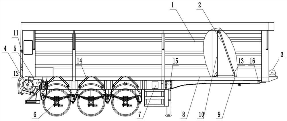
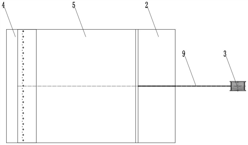
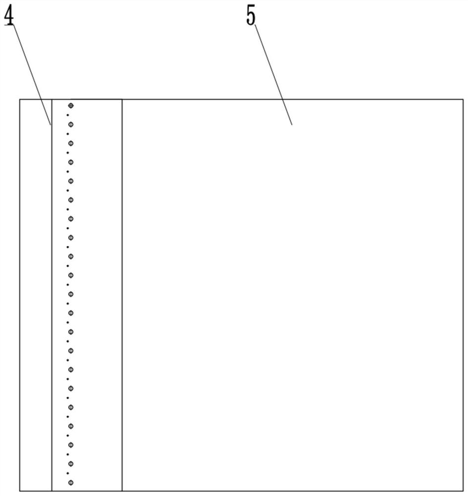
[0045] Such as figure 1 As shown, it is a schematic structural view of the conveyor belt push plate unloading device in Embodiment 1 of the present invention; as figure 2 As shown, it is a schematic view of the structure of the conveyor belt push plate unloading device in Embodiment 1 of the present invention; as image 3 As shown, it is a schematic diagram of the connection structure between the unloading roller and the unloading belt in the active recovery system in the conveyor belt push plate unloading device in Example 1 of the present invention; Figure 4 As shown, it is a schematic diagram of the connection structure between the unloading belt and the front plate in the active recovery system in the conveyor belt push plate unloading device in Embodiment 1 of the present invention; Figure 5 As shown, it is a schematic diagram of the connection structure between the front plate and the hydraulic winch in the active recovery system in the conveyor belt push plate unloa...


PUM


Abstract

The invention relates to a conveyor belt push plate unloading device, which belongs to the technical field of truck unloading and comprises a carriage, a front plate, a hydraulic winch, an unloading roller, an unloading belt, an axle, an electric control system, a hollowed-out bottom plate, a steel wire rope, a gap compensation mechanism, a rear door lock hook, a floating belt cleaning mechanism, a carriage guide plate, a flow guide groove and supporting legs, wherein one end of the unloading belt is connected with the unloading roller, the other end of the unloading belt is connected with one side of the front plate, the other side of the front plate is connected with the steel wire rope, and the other end of the steel wire rope is connected with the hydraulic winch. According to the conveyor belt push plate unloading device, the problem that most cargoes remain from the gap can be solved through the gap compensation mechanism, the flow guide groove can prevent the cargoes flowing out from remaining on the fender, the floating material cleaning mechanism on the front side can clean the residual cargoes on the cross beam, the floating belt cleaning scraper can clean sticky cargoes adhered to the unloading belt, and the two sets of mechanical lock hooks on the left side and the right side of the rear door lock hook ensure that the rear door is locked.

Description

technical field [0001] The invention relates to a conveyor belt push plate unloading device, which belongs to the technical field of truck unloading. Background technique [0002] As we all know, with the development of logistics, logistics companies will have a large number of goods, but the goods are transported by trucks. When transporting to the destination, the goods need to be removed. Rollover or backturn will cause the center of gravity of the vehicle to shift during the unloading process, which is prone to vehicle dumping and safety accidents, resulting in low reliability in use, and the truck unloading method in the prior art requires a large unloading time. The material space is easily restricted by the topography of the unloading site, resulting in more use limitations and poor practicability during use. [0003] The inventor applied for an invention patent and a utility model patent named "a conveyor belt push plate unloading device" on May 6, 2020, and filed t...

Claims


Application Information

Patent Timeline
Patent Type & Authority Applications(China)
IPC IPC(8): B60P1/38B60P1/36B60P1/00B62D25/18
CPCB60P1/38B60P1/365B60P1/00B62D25/18
Inventor 周磊贺东明杨晓龙
Owner TIANJIN TUQIANG SPECIAL AUTOMOBILE MFG CO LTD
Learn More