Transport vehicle for cement poles in vertical state

A vertical state, cement rod technology, applied in the direction of transportation and packaging, trolleys, motor vehicles, etc., can solve the problems of restrictions, large turning radius, and increase the difficulty of cement rods, so as to reduce the impact, reduce friction, and benefit the environment. Effect

Inactive Publication Date: 2021-08-06
JINAN CITY CHANGQING DISTRICT POWER SUPPLY CO OF STATE GRID SHANDONG ELECTRIC POWER CO +1
View PDF11 Cites 0 Cited by
  • Summary
  • Abstract
  • Description
  • Claims
  • Application Information

AI Technical Summary

Problems solved by technology

[0003] Through the above process, it can be known that when transporting cement poles, the existing technology is to directly transport the cement poles in the horizontal state. The cement poles in the horizontal state have a large radius of gyration when they turn, and they will be restricted when they are transported on narrow roads. Difficulty in transporting cement poles

Method used


Image

  • Transport vehicle for cement poles in vertical state
  • Transport vehicle for cement poles in vertical state
  • Transport vehicle for cement poles in vertical state

Examples


Embodiment 1

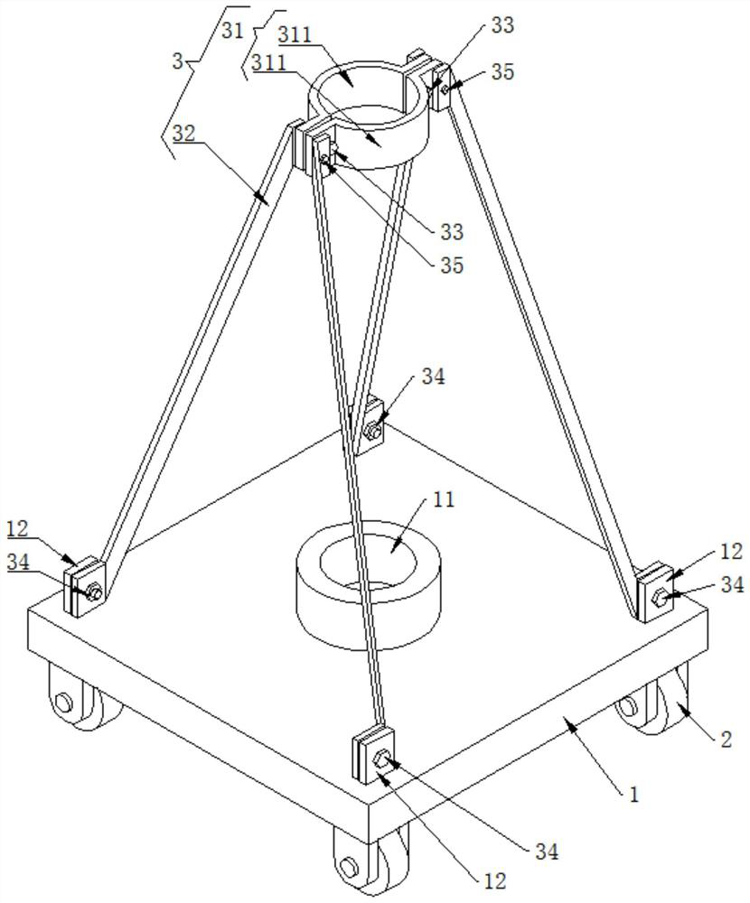
[0044] Such as figure 2 As shown, a cement rod transport vehicle in a vertical state includes a base 1 , moving wheels 2 , and a supporting mechanism 3 .

[0045] A moving wheel 2 is installed on the lower end surface of the base 1 .

[0046] The upper end surface of the base 1 is provided with a mounting groove 11, and the mounting groove 11 is used for inserting a cement rod in a vertical state.

[0047] A support mechanism 3 is provided above the base 1, and the support mechanism 3 is used to support the middle and upper part of the cement rod in a vertical state. The supporting mechanism 3 includes a hoop 31 and a supporting rod 32 . The hoop 31 includes at least two arc-shaped plates 311 for assembling into a ring structure. In this embodiment, the hoop 31 includes two arc-shaped plates 311, and the first fastener 33 adopts bolts. The shaped plates 311 are fastened together by bolts. There are at least two supporting rods 32. In this embodiment, there are four suppor...

Embodiment 2

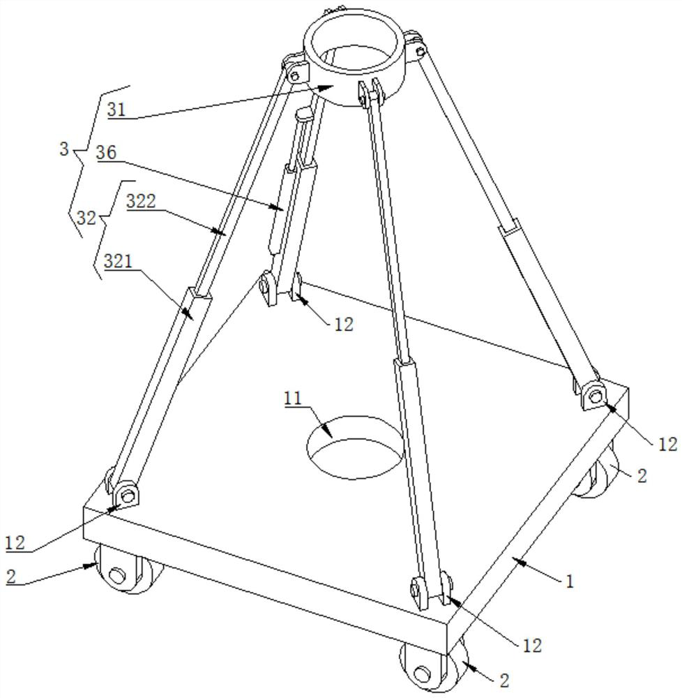
[0058] Such as image 3 As shown, a cement rod transport vehicle in a vertical state includes a base 1 , moving wheels 2 , and a supporting mechanism 3 .

[0059] A moving wheel 2 is installed on the lower end surface of the base 1 .

[0060] The upper end surface of the base 1 is provided with a mounting groove 11, and the mounting groove 11 is used for inserting a cement rod in a vertical state.

[0061] A support mechanism 3 is provided above the base 1, and the support mechanism 3 is used to support the middle and upper part of the cement rod in a vertical state. The supporting mechanism 3 includes a hoop 31 , a supporting rod 32 , and a supporting telescopic rod 36 . The hoop 31 is an annular structure. There are multiple supporting rods 32. In this embodiment, there are four supporting rods 32. These four supporting rods 32 are radially distributed with the installation groove 11 as the center of the circle. Each supporting rod 32 includes a supporting cover 321 and a...

Embodiment 3

[0073] Present embodiment 3 makes further improvement on the basis of embodiment 1 or embodiment 2:

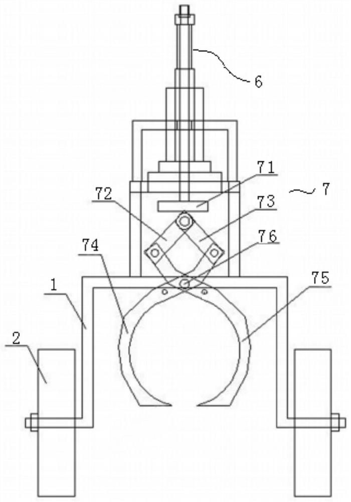
[0074] Such as Figure 4 with Figure 5 As shown, the upper end surface of the base 1 is provided with a feed hole 13, and the installation groove 11 communicates with the outside of the side wall of the base 1 through the feed hole 13, and the feed hole 13 is provided with an obliquely arranged guide plate 131 at an end close to the installation groove 11 , the lower end of the guide plate 131 is set away from the installation groove 11 , and the guide plate 131 is welded and fixed to the hole wall of the feed hole 13 .

[0075] A clamping mechanism 4 is provided on the upper surface of the base 1 , and the clamping mechanism 4 includes a fixed arc-shaped plate 41 , a movable arc-shaped plate 42 , and a driving assembly 43 .

[0076] The fixed arc-shaped plate 41 is arranged at the end of the installation groove 11 away from the feeding hole 13 , and the fixed arc-shaped pl...


PUM


Abstract

The invention discloses a vertical cement pole transport vehicle which comprises a base and moving wheels, the moving wheels are arranged on the lower end face of the base, a mounting groove for inserting a vertical cement pole is formed in the upper end face of the base, and a supporting mechanism is arranged above the base. The supporting mechanism comprises a hoop used for supporting the cement pole in the vertical state and a supporting rod used for supporting the hoop, and the hoop, the supporting rod and the base are sequentially connected from top to bottom. When the concrete pole is transported, turning can be carried out on a narrow road, the difficulty of transporting the concrete pole is reduced, the influence on road traffic is reduced, the construction cost is reduced, and environmental protection is facilitated.

Description

technical field [0001] The invention relates to the technical field of cement rod transportation, in particular to a cement rod transportation vehicle in a vertical state. Background technique [0002] In power grid construction, cement poles are indispensable. For the transportation of cement poles, the Chinese patent application number 201811246669.3 discloses a cement pole transportation device, such as figure 1 As shown, the device includes a base 1, a moving wheel 2, a lifting mechanism 6, and a tightening mechanism 7. The lower end surface of the base 1 is equipped with a moving wheel 2, and the holding mechanism 7 includes a connecting plate 71, a left connecting arm 72 and a right connecting arm 73 are hinged at the bottom of the connecting plate 71, and a right arc-shaped holding arm is hinged at the end of the left connecting arm 72. Arm 75 is hinged with left arc-shaped arm 74 at the end of right connecting arm 73, and the middle and upper parts of right arc-sha...

Claims


Application Information

Patent Timeline
Patent Type & Authority Applications(China)
IPC IPC(8): B62B3/10B62B3/04B62B5/00
CPCB62B3/104B62B3/04B62B5/00
Inventor 房启成张健张迎亮曲成涛万飞尹鹏王华
Owner JINAN CITY CHANGQING DISTRICT POWER SUPPLY CO OF STATE GRID SHANDONG ELECTRIC POWER CO
Why Eureka
Try Eureka