forward ejection stability augmentation device for horizontal fin of rotary AUV (Autonomous Underwater Vehicle)

A stability-increasing device and a horizontal technology, applied to equipment for increasing stability of ships, transportation and packaging, underwater operation equipment, etc. To avoid problems such as dynamic instability, achieve the effects of light weight, increased elongation, and small motion inertia

Active Publication Date: 2021-08-06
NORTHWESTERN POLYTECHNICAL UNIV
View PDF10 Cites 0 Cited by
  • Summary
  • Abstract
  • Description
  • Claims
  • Application Information

AI Technical Summary

Problems solved by technology

However, this technical solution cannot be applied to the existing rotary AUV due to the need to install the main and ailerons, and its internal space and shape have undergone major changes.
Secondly, its dual-mode navigation of gliding and high-speed direct flight cannot match most of the existing rotary AUVs that rely on power systems such as propellers, and its applicability is greatly limited.
At the same time, this technical solution is a related solution to the dynamic instability of high-speed direct navigation, and cannot effectively solve the problem of AUV low-speed navigation instability under low-speed or micro-speed conditions below 3kn.

Method used


Image

  • forward ejection stability augmentation device for horizontal fin of rotary AUV (Autonomous Underwater Vehicle)
  • forward ejection stability augmentation device for horizontal fin of rotary AUV (Autonomous Underwater Vehicle)
  • forward ejection stability augmentation device for horizontal fin of rotary AUV (Autonomous Underwater Vehicle)

Examples


Embodiment approach

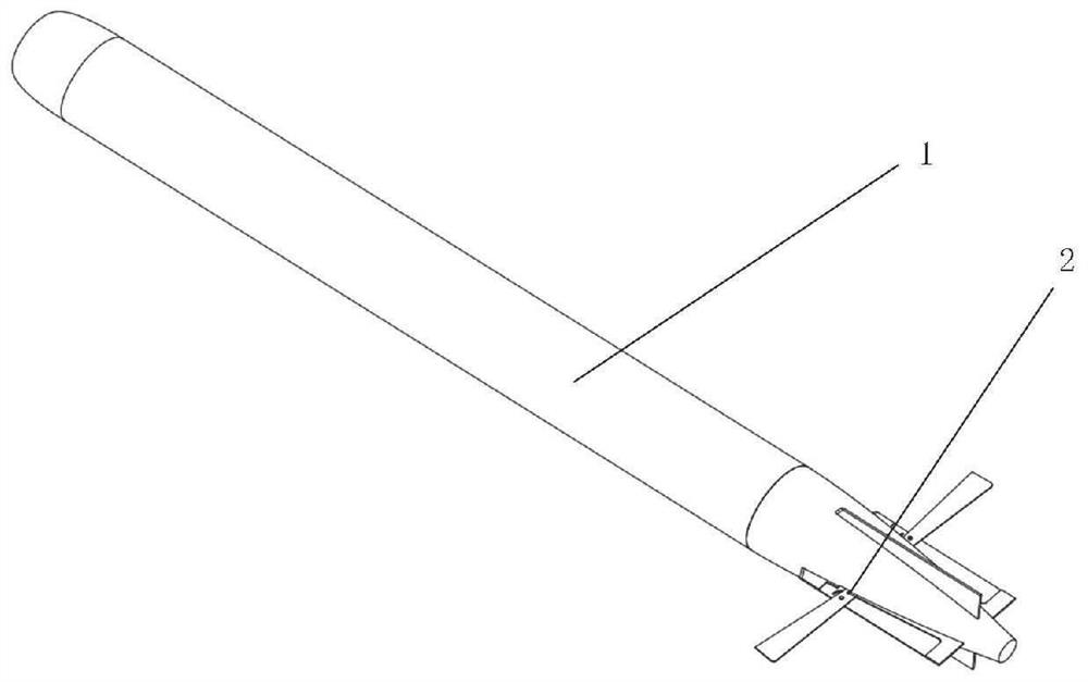
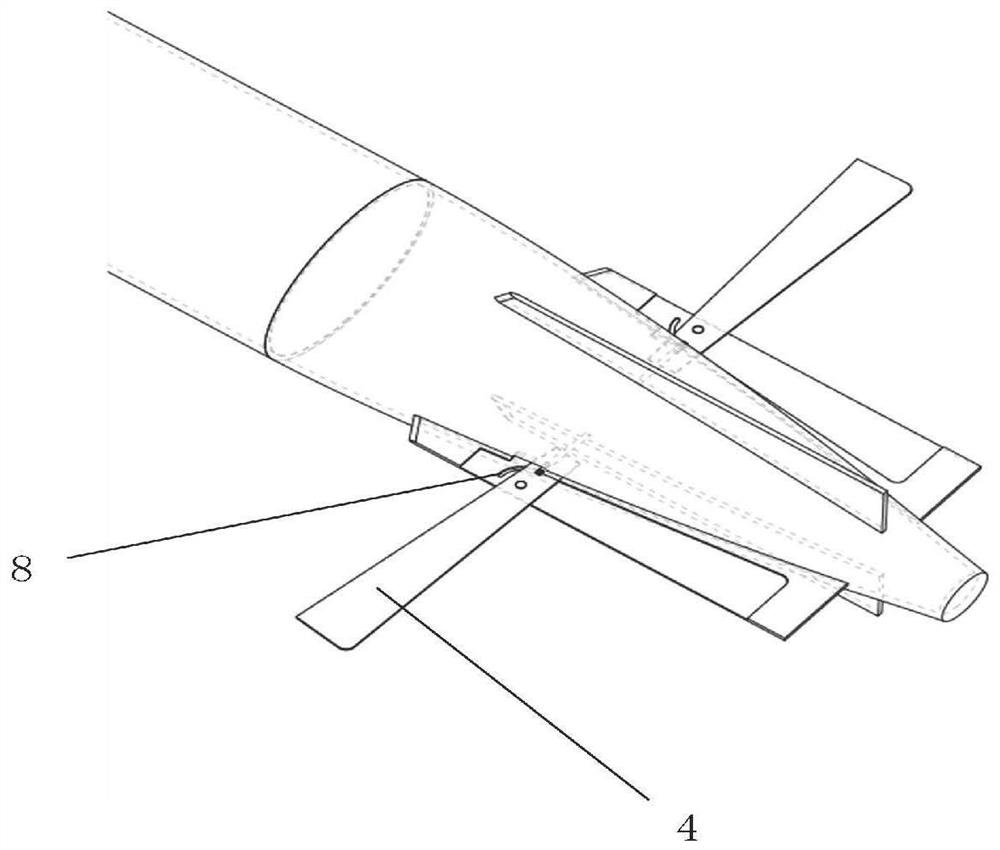
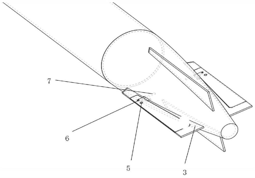
[0045] Such as Figure 5 As shown in the schematic diagram of the non-pop-up state of the forward pop-up stabilization device of the horizontal fin, when the working state does not require high handling stability, the triangular movable fin plate 4 is in the position groove of the horizontal fin plate of the fixed cross-shaped fin rudder mechanism 3, through the hydraulic pressure Bar 7, limit slideway 8 and other control mechanism guarantee that triangular movable fin plate 4 is fixed. When there is a high stability requirement for the gyratory AUV1, such as Figure 6 As shown in the schematic diagram of the pop-up state of the horizontal fin forward pop-up stabilization device, the hydraulic pump starts to work, drives the hydraulic rod 7 to move, and pushes the triangular movable fin plate 4 to rotate along the limit slideway 8. When the movable fin plate 4 rotates to the designated working position , the hydraulic pump stops working, and the hydraulic rod 7 stops moving. ...


PUM


Abstract

The invention discloses a forward ejection stability augmentation device for a horizontal fin of a rotary AUV (Autonomous Underwater Vehicle), and belongs to the fields of hydromechanics and maneuverability and stability of underwater vehicles. The device comprises an AUV cross fin rudder and horizontal pop-up movable fin plate mechanisms arranged on horizontal fins of the AUV cross fin rudder, and the left horizontal pop-up movable fin plate mechanism and the right horizontal pop-up movable fin plate mechanism are symmetrically arranged on the horizontal fins on the two sides; the left horizontal ejection movable fin plate mechanism comprises a movable fin plate and a hydraulic ejection mechanism, the front end of the movable fin plate is installed on the end face of the horizontal fin through the hydraulic ejection mechanism, the movable fin plate can be controlled to rotate through the hydraulic ejection mechanism, and the action that the movable fin plate is ejected outwards or withdrawn relative to the horizontal fin is achieved; the hydraulic ejection mechanism is located at the front end of the horizontal fin. The speed reduction effect can be rapidly achieved through the ejection stability augmentation device, and the speed reduction effect is improved by 30%; meanwhile, the area of the control fin plate is increased by 70%, and the extension length of the fin plate is increased by 460%. According to the invention, the wetting area of the stabilizing fin is increased after the horizontal fin pops up.

Description

technical field [0001] The invention belongs to the fields of hydrodynamics, maneuverability and stability of underwater vehicles, and in particular relates to a forward ejection stabilization device of a rotary AUV horizontal fin. Background technique [0002] With the rapid development of human society, the demand for energy, food and other resources has greatly increased, and most of the land resources have been consumed by humans. The ocean, which covers four-fifths of the earth's surface, contains rich resources. The ocean is the largest on the earth's surface. Physical Geographical Unit Therefore, the 21st century is the ocean century, and the ocean will become the main field of competition for international development, including new economic competition guided by high-tech. How to explore and exploit marine resources has become one of the most popular issues in this century. It has decisive strategic significance in economy, politics and military. As the main tool o...

Claims


Application Information

Patent Timeline
Patent Type & Authority Applications(China)
IPC IPC(8): B63B39/06B63C11/52
CPCB63B39/062B63C11/52
Inventor 杜晓旭刘鑫王鹏潘光宋保维
Owner NORTHWESTERN POLYTECHNICAL UNIV
Why Eureka
Try Eureka