Novel falling type empty frame conveying device

A conveying device, drop-type technology, applied in the direction of conveyors, conveyor objects, transportation and packaging, etc., can solve the problems of high failure rate, complex structure, difficult synchronous drive control of multiple sets of equipment, etc., to reduce the overall failure rate, High synchronization performance and reduced control device effects

Pending Publication Date: 2021-08-06
SHENZHEN MAXVISION TECH
View PDF0 Cites 0 Cited by
  • Summary
  • Abstract
  • Description
  • Claims
  • Application Information

AI Technical Summary

Problems solved by technology

[0003] The empty frame conveying device is an important mechanism for the automatic recycling of empty pallets during baggage security inspection, that is, during baggage security inspection, the baggage is placed in the empty frame, conveyed by an external conveyor, and after passing through the security inspection machine, the baggage is taken out after the end of the empty pallet. That is, the empty frame needs to be transported to the initial position for reuse. Since the luggage frame is not connected to the external conveyor, it is necessary to use the empty frame conveying device to transfer the empty frame up and down and then transport it back to the initial position. At present, the automatic travel check-back box at domestic airports The system has configurations, and the existing empty frame conveying devices are mostly screw conveying structures, drop conveying mechanisms or swing arm conveying mechanisms, etc., but the structure of the existing empty frame conveying devices is relatively complicated, and it is difficult for multiple sets of equipment to drive synchronously control, and the failure rate is high

Method used


Image

  • Novel falling type empty frame conveying device
  • Novel falling type empty frame conveying device
  • Novel falling type empty frame conveying device

Examples


Embodiment Construction

[0030] In order to enable those skilled in the art to better understand the technical solutions of the present invention, the present invention will be further described in detail below in conjunction with the accompanying drawings.

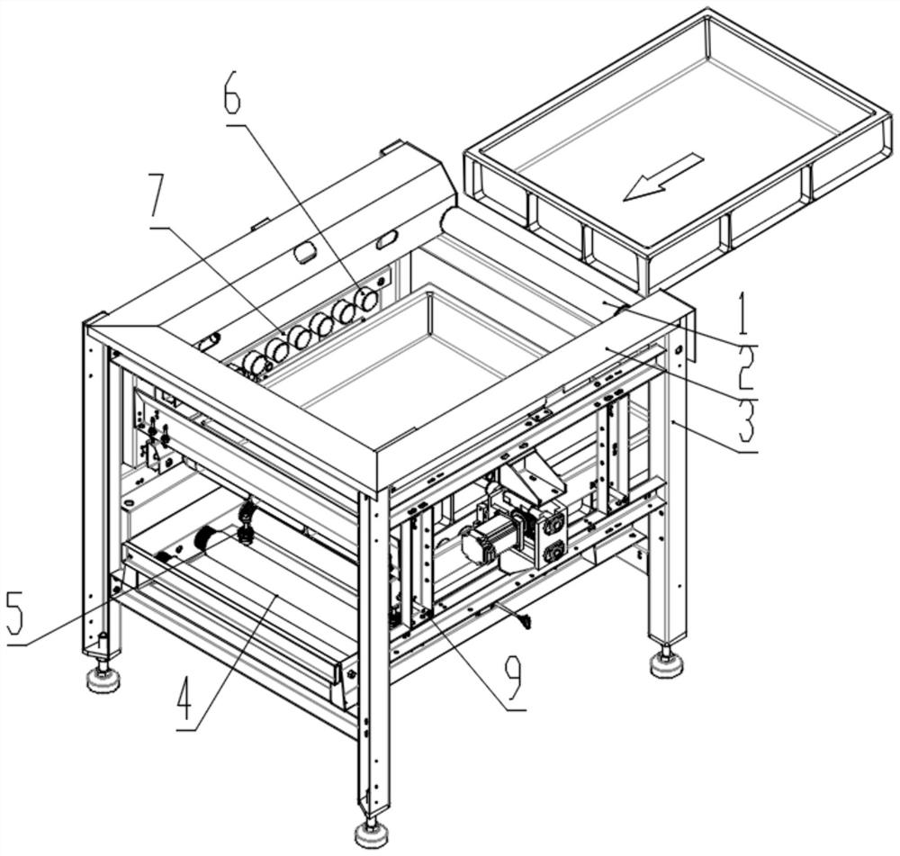
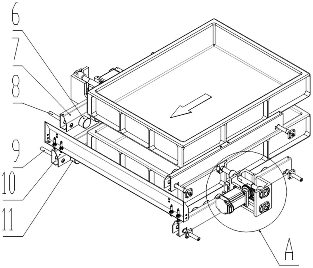
[0031] The present invention provides such Figure 1-4 A new drop-type empty frame conveying device shown includes a frame 3, the top of the frame 3 is fixedly connected with a guide groove 2, and one end of the guide groove 2 is rotatably installed with a transition electric drum 1, and the machine Both sides of the inner top of the frame 3 are provided with an upper material receiving plate 7, and both sides of the inner middle part of the frame 3 are provided with a lower material receiving plate 10, and the two lower layer material receiving plates 10 are respectively located at the two upper layers. At the bottom of the material plate 7, the frame 3 is fixedly equipped with an upper guide rod 8 near the position of the upper layer material r...


PUM


Abstract

The invention discloses a novel falling type empty frame conveying device, and relates to the technical field of conveying equipment. The novel falling type empty frame conveying device comprises racks, guide grooves are fixedly connected to the tops of the racks, a transition electric roller is rotationally installed at one end of one guide groove and one end of the other guide groove, upper-layer material receiving plates are arranged on the two sides of the tops of the inner sides of the racks, lower-layer material receiving plates are arranged on the two sides of the middles of the inner sides of the racks, the two lower-layer material receiving plates are located at the bottoms of the two upper-layer material receiving plates correspondingly, and upper-layer guide rods are fixedly installed in the positions, close to the upper-layer material receiving plates, of the racks. The two racks are controlled to synchronously rotate in different directions, then the two upper-layer material receiving plates and the two lower-layer material receiving plates are synchronously controlled to synchronously move in opposite directions, layered falling control over empty frames is achieved, finally, the empty frames are conveyed to the conveying front end through a lower-layer conveyor, safe falling of the empty frames is guaranteed, the synchronous performance of falling control over the empty frames is higher, control equipment is reduced, and the overall failure rate of the device is reduced.

Description

technical field [0001] The invention relates to the technical field of conveying equipment, in particular to a novel drop-type empty frame conveying device. Background technique [0002] Conveying equipment is a kind of equipment for short-distance conveying of objects. The conveyor is affected by the technological progress of machinery manufacturing, electrical machinery, chemical industry and metallurgy industry. Material handling between enterprises and even between cities has become an indispensable part of the mechanization and automation of material handling systems. [0003] The empty frame conveying device is an important mechanism for the automatic recycling of empty pallets during baggage security inspection, that is, during baggage security inspection, the baggage is placed in the empty frame, conveyed by an external conveyor, and after passing through the security inspection machine, the baggage is taken out after the end of the empty pallet. That is, the empty ...

Claims


Application Information

Patent Timeline
Patent Type & Authority Applications(China)
IPC IPC(8): B65G47/57
CPCB65G47/57B65G2201/0267
Inventor 徐志祥张刚潘淳池苗应亮
Owner SHENZHEN MAXVISION TECH
Why Eureka
Try Eureka