
Device for treating sewage by utilizing electromagnetic field rotational flow cavitation technology

A technology of technical treatment and electromagnetic field, applied in the fields of magnetic field/electric field water/sewage treatment, special compound water treatment, oxidized water/sewage treatment, etc. Low problems, to achieve the effect of convenient operation, cost saving and efficient mass transfer

Inactive Publication Date: 2021-08-06
陈尚熙
View PDF0 Cites 1 Cited by
  • Summary
  • Abstract
  • Description
  • Claims
  • Application Information

AI Technical Summary

Problems solved by technology

This requirement puts forward relatively strict requirements on the equipment and methods for implementing heterogeneous reactions, which must simultaneously meet high-efficiency mass transfer, synchronous catalysis, and synchronous reactions, and the energy consumption for implementing heterogeneous reactions should be as low as possible. The consumption should be as low as possible, and the existing technology and equipment are difficult to meet such stringent requirements. This situation has seriously restricted the wide application of heterogeneous reaction technology in industry, agriculture, environmental protection and other industries for a long time.

Method used


Image

  • Device for treating sewage by utilizing electromagnetic field rotational flow cavitation technology
  • Device for treating sewage by utilizing electromagnetic field rotational flow cavitation technology
  • Device for treating sewage by utilizing electromagnetic field rotational flow cavitation technology

Examples


Embodiment 1

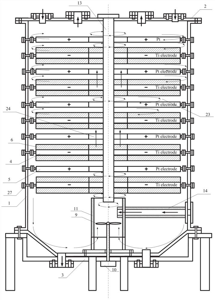
[0040] This embodiment provides a device for treating sewage by using electromagnetic field swirl cavitation technology. Under electromagnetic field conditions, the electro-adsorption technology, electro-catalysis and hydraulic cavitation technology are combined, which is an efficient mass transfer and electro-adsorption technology based on multi-phase flow. Integrated multiphase flow electrochemical reaction device for regeneration, synchronous electrocatalysis, and synchronous electrochemical reaction; such as figure 1 As shown, it includes an electromagnetic field generating device 46, a swirl generating device 47, and a reactor vessel. The electromagnetic field generating device 46 is installed inside the reactor vessel, and the swirl generating device 47 is installed at the bottom of the reactor vessel.

[0041] In this embodiment, the reactor vessel includes a tank body 1, a top cover plate 2, a bottom cover plate 3 and a support seat, the tank body 1 is a cylindrical str...

Embodiment 2

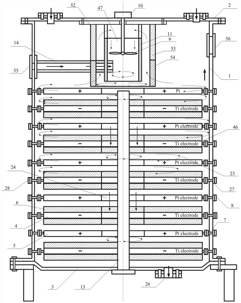
[0052] This embodiment provides a device for treating sewage using electromagnetic field cyclone cavitation technology, such as figure 2 As shown, the structure of the second embodiment is basically the same as that of the first embodiment. The difference between the second embodiment and the first embodiment is that the swirl generating device 47 is installed on the top of the reactor tank 1, and the driving motor 10 is installed on the top cover. The high-energy generator 13 is installed at the bottom of the reactor tank 1, one end of the high-energy generator 13 is fixed to the bottom cover plate 3, and the other end extends upward into the guide tube 11 for a certain distance. A hollow cylindrical filter screen 52 is disposed outside the swirl generating device 47 , and the cylindrical filter screen 52 includes a mesh-free partition plate 53 and a mesh-shaped filter mesh 54 located at the lower part of the mesh-free partition plate 53 .

[0053] The side surface of the sw...

Embodiment 3

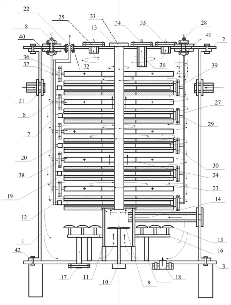
[0055] This embodiment provides a device for treating sewage using electromagnetic field cyclone cavitation technology, such as image 3 - shown in Figure 10, including electromagnetic field generating device 46, swirl generating device 47, reactor vessel, electromagnetic field generating device 46 is installed inside the reactor vessel, and swirl generating device 47 is installed at the bottom of the reactor vessel.

[0056] The reactor container includes a tank body 1, a top cover plate 2, a bottom cover plate 3 and a support seat, and the tank body 1 is a cylindrical structure; such as Image 6 As shown, the side of the tank body 1 is connected with a plurality of tank body insertion pipes 21 . The top cover plate 2 is installed on the top of the tank body 1, and the bottom cover plate 3 is installed on the bottom of the tank body 1; Bottom cover 3 is connected. The top cover plate 2 is provided with a water outlet A25 and a water outlet B26. The water outlet A25 is fixed...


PUM


Abstract

The invention discloses adevice for treating sewage by utilizing electromagnetic field rotational flow cavitation technology. According to the technical scheme, the device comprises an electromagnetic field generating device, a rotational flow generating device and a reaction kettle container, wherein the electromagnetic field generating device is installed in the reaction kettle container, and the rotational flow generating device is installed at the bottom and / or the top of the reaction kettle container; the electromagnetic field generating device comprises a plurality of anode electrode plates and cathode electrode plates which are alternately arranged at intervals; fluid can enter the electromagnetic field generating device through the rotational flow generating device, and a fluid channel perpendicular to the central axis of the electrode plates and a fluid channel horizontal to the central axis of the electrode plates are formed. In the heterogeneous mass transfer process, the degree of supersaturation of mass transfer substances is reduced through multiple electrochemical reactions, so that a large number of insoluble substances existing in the multiphase flow fluid are continuously supplemented into the main fluid of the multiphase flow fluid through the mass transfer process, and reaction substances are continuously provided for later electrochemical reactions; and a circular reaction chain between heterogeneous mass transfer and electrochemical reaction is established, so that the efficiency is improved, and the cost and energy consumption are reduced.

Description

technical field [0001] The invention relates to the technical field of sewage treatment, in particular to a device for treating sewage by using electromagnetic field swirling cavitation technology. Background technique [0002] Heterogeneous reaction, also known as "heterogeneous reaction", means that the reactants are components of two or more phases (solid and gas, solid and liquid, two immiscible liquids), or A general term for a chemical reaction in which one or more reactants are carried out at an interface (eg, on the surface of a solid catalyst). In chemical, pharmaceutical, environmental protection and other fields, heterogeneous reactions are often used to complete chemical reactions that cannot be achieved by general homogeneous reactions. Compared with general homogeneous reactions, heterogeneous reactions have fast reaction rates, high catalytic efficiency, and The characteristics of high strength, especially the easy separation of reactants, for example, the us...

Claims


Application Information

Patent Timeline
Patent Type & Authority Applications(China)
IPC IPC(8): C02F9/12
CPCC02F1/36C02F1/38C02F1/48C02F1/72C02F9/00C02F2201/002C02F2201/48C02F2303/14C02F2305/023
Inventor 不公告发明人
Owner 陈尚熙
Learn More