Prefabricated stand column

A column and pre-embedded technology, applied in the direction of columns, piers, pillars, etc., can solve the problems of low precision of prefabricated columns, inability to cover beams, small box beams and other problems, and achieve the effect of convenient insertion, reduced operation and good coordination.

Inactive Publication Date: 2021-08-06
绍兴市城投建筑工业化制造有限公司
View PDF8 Cites 0 Cited by
  • Summary
  • Abstract
  • Description
  • Claims
  • Application Information

AI Technical Summary

Problems solved by technology

[0004] The present invention overcomes the low precision of the current prefabricated column and cannot cooperate well with the cover beam and the small box girder, and provides a prefabricated column. The precise positioning of the horizontal ribs is carried out in the column sleeve, avoiding the collision between the steel bars and reducing the waste of raw materials

Method used


Image

  • Prefabricated stand column
  • Prefabricated stand column
  • Prefabricated stand column

Examples


Embodiment 1

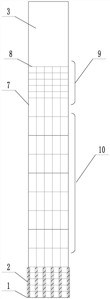
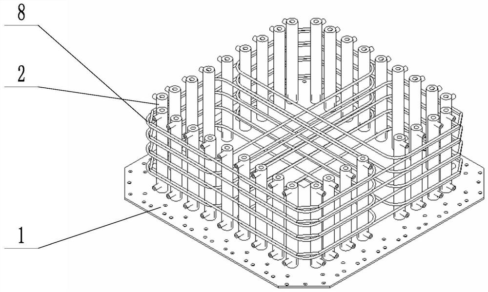
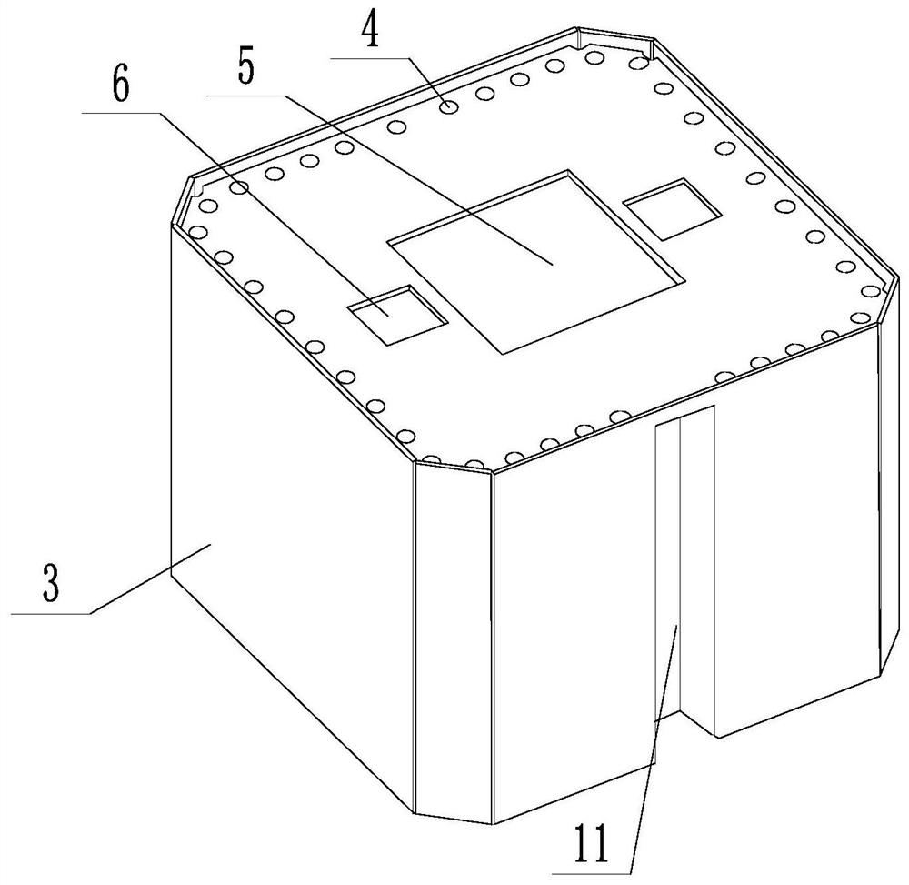
[0045] A prefabricated column such as Figures 1 to 3 As shown, it is formed by pouring concrete, including the bottom positioning plate 1 and the top embedded column sleeve 3, and the positioning plate 1 is fixedly connected with the grouting sleeve 2 (the internal structure of the grouting sleeve 2 is the prior art and will not be repeated here). The grouting sleeve is arranged near the outer edge of the positioning plate. The positioning plate 1 is provided with an opening corresponding to and connected to the grouting sleeve 2. Between the positioning plate 1 and the pre-embedded column sleeve 3, there are longitudinally arranged main ribs 7 and Annular stirrups 8 arranged along the cross section. The column is provided with a thickened stirrup section 9 and a standard stirrup section 10 in the axial direction, and the spacing between the adjacent annular stirrups 8 in the thickened stirrup section 9 is denser than that of the standard stirrup section 10. The rib densific...

Embodiment 2

[0051] This embodiment adds the following features on the basis of Embodiment 1:

[0052] Such as Image 6 , 7 , 8, the inner diameter of the middle part of the grouting sleeve 2 gradually increases from top to bottom, and a positioning piece is inserted in the grouting sleeve 2, and the positioning piece includes a positioning piece body 17 whose diameter is smaller than the inner diameter of the grouting sleeve 2 and 4 abutment pins 18 that are rotationally connected to the side wall of the locator body 17 in the circumferential direction. The side wall of the locator body 17 is provided with a concave ball seat 19, and the rotating end of the abutment pin 18 is inserted into the concave There is a gap between the ball seat 19 and the concave ball seat 19; the locator moves in one direction on the grouting sleeve 2:

[0053] When the positioning piece is inserted into the grouting sleeve 2 from bottom to top, the abutment pin 18 rotates and retracts toward the axis of the ...

Embodiment 3

[0061] On the basis of embodiment 2, it also has the following characteristics:

[0062] Such as Figure 9 As shown, the concave ball seat 19 is provided with an elastic block 20, and the elastic block 20 drives the abutment pin 18 to expand in the radial direction of the positioning member. Overcome the elastic piece when inserting the positioning piece. When inserting the main rib 7, the elastic block 20 drives the abutment pin 18 to expand, and the effect of one-way movement is better.


PUM


Abstract

The invention discloses a prefabricated stand column and aims to overcome the defects that an existing prefabricated stand column is low in precision and cannot be well matched with a bent cap and a small box girder. The prefabricated stand column is formed by concrete pouring and comprises a positioning plate at the bottom and a pre-embedded column sleeve at the top, a grouting sleeve is fixedly connected to the positioning plate and arranged at the position, close to the outer edge, of the positioning plate, and the positioning plate is provided with an open hole corresponding to and communicated with the grouting sleeve; longitudinally arranged main reinforcements and annular stirrups arranged along the cross section are arranged between the positioning plate and the pre-embedded column sleeve, the main reinforcements are inserted into the grouting sleeve, the other ends of the main reinforcements are positioned through the embedded column sleeve, and the annular stirrups hoop the main reinforcements and the grouting sleeve. The arrangement precision of the main reinforcements is higher through the pre-embedded column sleeve, the main reinforcements are better matched with other prefabricated parts, meanwhile, collision between the reinforcements is avoided, and the waste of raw materials is reduced.

Description

technical field [0001] The invention relates to the field of bridge construction, more specifically, it relates to a prefabricated column. Background technique [0002] Prefabricated steel-sleeved column products have a wide range of application value in the field of bridge construction and construction research, but traditional cast-in-place column products are difficult to guarantee the accuracy of components, and cannot accurately splice cover beams, columns, and small box girders. At the same time, the site construction conditions are high, which will have a certain degree of impact on the surrounding residents' living conditions and traffic conditions. The disadvantages of on-site construction are: the accuracy is difficult to grasp, which affects the stress of the finished product, and the strength at the time of design cannot be realized, which reduces the safety of the bridge; the waiting time is long, and it is necessary to wait for the strength of the cast-in-place...

Claims


Application Information

Patent Timeline
Patent Type & Authority Applications(China)
IPC IPC(8): E01D19/00E01D21/00E04C3/34E04C5/16E04C5/01E04C5/06E04G21/02
CPCE01D19/00E01D21/00E04C3/34E04C5/16E04C5/162E04C5/01E04C5/06E04G21/02
Inventor 宁英杰赵颖超龚世文白丽辉迟文明黄祎涵金一峰潘龙胜李清云陈旭光
Owner 绍兴市城投建筑工业化制造有限公司
Why Eureka
Try Eureka