Eureka AIR delivers breakthrough ideas for toughest innovation challenges, trusted by R&D personnel around the world.

Mounting structure and mounting method for hidden door handle of automobile

A technology of installation structure and installation method, which is applied in the field of hidden handles, can solve the problems of poor appearance gap between the door handle and the outer panel, complicated assembly process, and long time consumption, and achieve the effect of convenient appearance gap, simple size adjustment, and high efficiency

Active Publication Date: 2021-08-06
NINGBO XINTAI MACHINERY
View PDF16 Cites 2 Cited by
  • Summary
  • Abstract
  • Description
  • Claims
  • Application Information

AI Technical Summary

Problems solved by technology

[0003] At present, the traditional installation method is that the installation and positioning structure are all on the support plate of the car door, and the outer plate is only a hole. If there is an assembly error between the door outer plate and the support plate, the error will be accumulated to the appearance gap between the door handle and the outer plate on, resulting in a poor apparent gap between the door handle and the outer panel
[0004] There is also a way for the main engine factory to use auxiliary tooling ( Figure 11 and 12 shown) to ensure the gap between the door handle and the outer panel. This solution has a good control effect on the gap, but it needs to develop auxiliary tooling, and the assembly process is too complicated. It is necessary to assemble the auxiliary tooling on the door handle first, and then install the door handle It is assembled on the door sheet metal together with the auxiliary tooling. After the assembly is completed, the auxiliary tooling needs to be removed
The entire assembly process takes a long time

Method used


Image

  • Mounting structure and mounting method for hidden door handle of automobile
  • Mounting structure and mounting method for hidden door handle of automobile
  • Mounting structure and mounting method for hidden door handle of automobile

Examples


Embodiment Construction

[0032] Below in conjunction with specific embodiment, further illustrate the present invention. It should be understood that these examples are only used to illustrate the present invention and are not intended to limit the scope of the present invention. In addition, it should be understood that after reading the teachings of the present invention, those skilled in the art may make various changes or modifications to the present invention, and these equivalent forms also fall within the scope defined by the appended claims of the present application.

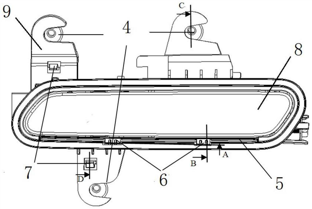
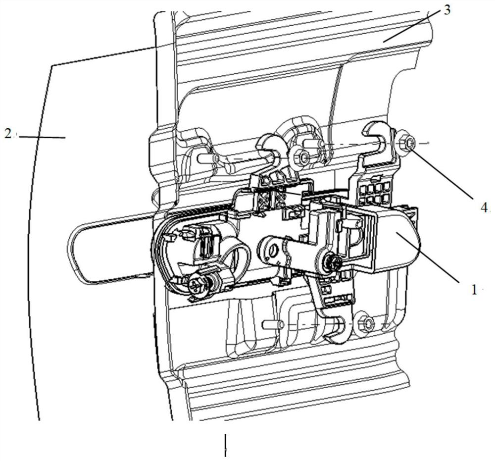
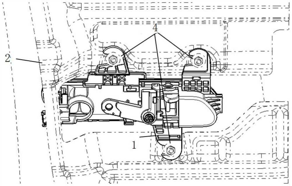
[0033] An automobile concealed door handle installation structure, comprising a handle base 1, a hook foot 9 and an outer handle cover 8, the upper and lower parts of the handle base 1 are provided with a hook foot 9, and the hook foot 9 is not less than Three, the right side of the end of the hook foot 9 is provided with a Y-direction positioning opening, the front side of the handle base 1 is provided with a handle outer cove...


PUM


Abstract

The invention provides a mounting structure and a mounting method for a hidden door handle of an automobile. The mounting structure comprises a handle base, at least three hook feet and a handle outer cover plate, wherein the at least three hook feet are arranged on the upper portion and the lower portion of the handle base, Y-direction positioning openings are formed in the right sides of the tail ends of the hook feet, the handle outer cover plate is arranged on the front side of the handle base, the handle base is installed at the position of a car door metal plate support, positioning grooves are formed in the lower portion of the handle outer cover plate side by side, transverse supporting ribs corresponding to the lower side of the handle outer cover plate are arranged on the handle base, and a car door outer plate is arranged on the front side of the car door metal plate support. The mounting structure has the advantages that the appearance clearance is convenient to control, the assembly cost is reduced, the assembly difficulty is reduced, the assembly efficiency is improved, the handle is prevented from sinking, the matching clearance is adjustable, and the reliability is good.

Description

technical field [0001] The invention relates to the technical field of hidden handles, in particular to an installation structure and an installation method of an automobile hidden door handle. Background technique [0002] With the development trend of intelligence and electrification in the automobile industry, hidden door handles are more and more widely used in automobiles, especially new energy vehicles. The traditional door handle protrudes outside the door sheet metal, and the degree of matching with the outer door panel has little effect on the appearance of the entire door, and the contour size of the door handle circumference is not high. The hidden door handle is embedded in the outer panel of the car door, and the consistency with the peripheral clearance of the groove in the outer panel of the door directly affects the appearance quality of the door, so the control requirements for the peripheral clearance are also increased accordingly. [0003] At present, th...

Claims


Application Information

Patent Timeline
Patent Type & Authority Applications(China)
IPC IPC(8): E05B79/06E05B85/10
CPCE05B79/06E05B85/103Y02T10/40
Inventor 蒋佳俊万财东金英杰白永峰相斌斌朱郭豪华建波
Owner NINGBO XINTAI MACHINERY
Why Eureka
Eureka Blog
Learn More