Vacuum pump one-way valve assembly

A one-way valve, vacuum pump technology, applied in the valve device, control valve, functional valve type and other directions, can solve the problems of inconvenient force-driven size adjustment control, poor opening and closing response efficiency, etc., to improve the force-driven response efficiency. Effect

Pending Publication Date: 2021-08-06
CHONGQING YUNHAI MACHINERY MFG
View PDF8 Cites 1 Cited by
  • Summary
  • Abstract
  • Description
  • Claims
  • Application Information

AI Technical Summary

Problems solved by technology

[0003] However, the structure of the check valve assembly of the prior art vacuum pump is relatively simple, and it is inconvenient to adjust and control the force-driven magnitude of the periodic opening and closing of the hemispherical valve core during use, so that the response efficiency of opening and closing after a certain deformation of the spring is generated. poor

Method used


Image

  • Vacuum pump one-way valve assembly
  • Vacuum pump one-way valve assembly
  • Vacuum pump one-way valve assembly

Examples


Embodiment 1

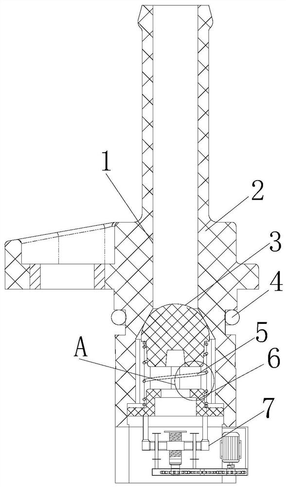
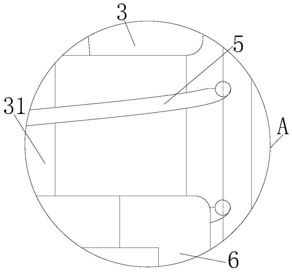
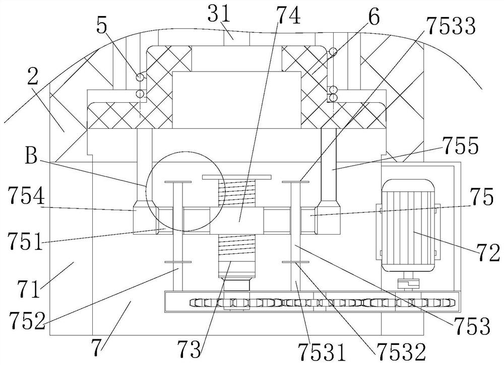
[0029] see figure 1 and figure 2 , a vacuum pump check valve assembly of the present invention, assembly main body 1, valve body 2, hemispherical valve core 3, O-shaped sealing ring 4, spring 5, valve seat 6 and adjustment structure 7, the air flow channel inside the valve body 2 The hemispherical valve core 3 is installed, and the outer middle side of the valve body 2 is connected with an O-ring 4. The outer surface of the bottom side of the hemispherical valve core 3 is in elastic contact with the valve seat 6 through the spring 5, and the valve seat 6 is slidably connected to the inner side of the valve body 2. The bottom side of the valve body 2 is connected with an adjustment structure 7, and the adjustment control is performed through the adjustment structure 7. A pillar 31 is embedded in the middle side of the bottom of the hemispherical valve core 3, and the bottom of the pillar 31 is inserted into the inner side of the valve seat 6 to fix it, and it plays a role of s...

Embodiment 2

[0032]A vacuum pump check valve assembly of the present invention, the bottom side of the hemispherical valve core 3 is provided with an inward inclination angle, the inner top side of the spring 5 is wrapped at the inclination angle of the bottom side of the hemispherical valve core 3, and the inner bottom side of the spring 5 is wrapped in the valve The outer surface of the top side of the seat 6 is supported by the spring 5 to provide elastic force for the hemispherical valve core 3. The channel opened inside the valve body 2 gradually increases from top to bottom, and the connection between the channel and the hemispherical spool 3 is conical. Table-shaped structure, the closedness after being adjusted is increased, the valve seat 6 is in a convex structure, and the valve seat 6 is arranged in a section of the chute on the bottom side of the valve body 2 and is longitudinally slidably connected with it, which is beneficial to the valve seat 6. The height position is adjuste...


PUM


Abstract

The invention discloses a vacuum pump one-way valve assembly. The one-way valve assembly comprises an assembly body, a valve body, a hemispherical valve element, an O-shaped sealing ring, a spring, a valve seat and an adjusting structure. According to the vacuum pump one-way valve assembly, the adjusting structure is optimally arranged, a servo motor serves as a power source, a threaded rod stably rotates on a supporting frame sleeve through meshing transmission among a first gear, a second gear and a third gear, and the threaded rod is matched with an inner threaded block to drive a sheet bar to move on a rod body by the height position; and limiting supporting is achieved under the action of a lower supporting piece and an upper supporting piece, a first vertical rod and a second vertical rod on the sheet bar drive the valve seat to move by the height position in the valve body, and therefore the supporting position of the valve seat on the hemispherical valve element through the spring is adjusted, and the stress driving reaction efficiency of periodic opening and closing of the hemispherical valve element is improved to a certain degree.

Description

technical field [0001] The invention relates to the related field of automobile vacuum pumps, in particular to a vacuum pump check valve assembly. Background technique [0002] The car vacuum pump is connected with the vacuum booster, which is used to suck the air in the vacuum booster and increase the vacuum degree of the vacuum booster. According to the principle of the vacuum booster, the higher the vacuum level, the greater the power boost, step on the brake pedal The greater the braking force; the vacuum pump usually uses the internal check valve assembly to achieve periodic opening and closing. [0003] However, the structure of the check valve assembly of the prior art vacuum pump is relatively simple, and it is inconvenient to adjust and control the force-driven magnitude of the periodic opening and closing of the hemispherical valve core during use, so that the response efficiency of opening and closing after a certain deformation of the spring is generated. poor. ...

Claims


Application Information

Patent Timeline
IPC IPC(8): F16K15/18F16K15/06
CPCF16K15/18F16K15/063
Inventor 王帆何万飞吴红君金润
Owner CHONGQING YUNHAI MACHINERY MFG
Why Eureka
Try Eureka