
LED packaging structure and LED light source device

A technology of LED packaging and reflective cups, which is applied to the semiconductor devices of light-emitting elements, light sources, light source fixing and other directions, can solve the problems of increased difficulty in operating LED lights, and achieve the effects of reducing friction area, firm cooperation, and convenient adjustment and operation.

Active Publication Date: 2021-08-06
佛山市其利照明电器有限公司
View PDF14 Cites 2 Cited by
  • Summary
  • Abstract
  • Description
  • Claims
  • Application Information

AI Technical Summary

Problems solved by technology

[0002] The package structure mainly focuses on the form and category of the package, the material of the substrate, the shell, and the leads, emphasizing its important role in protecting the chip, enhancing the electrothermal performance, and facilitating the assembly of the whole machine. However, most of the existing LED package structures are in pursuit of higher sealing. Performance, the outer structure such as the bottom plate, the shell and the lampshade are sealed by integral molding, welding or sealant. Although the sealing performance of the LED lamp is improved, the operation difficulty will increase when the LED lamp needs to replace parts; moreover, large Most LED lamps still have defects in adjusting the direction of light irradiation internally; therefore, it is necessary to design an LED packaging structure and LED light source device

Method used


Image

  • LED packaging structure and LED light source device
  • LED packaging structure and LED light source device
  • LED packaging structure and LED light source device

Examples


Embodiment Construction

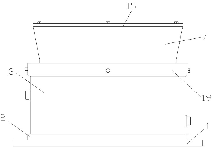
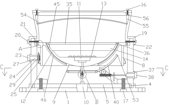
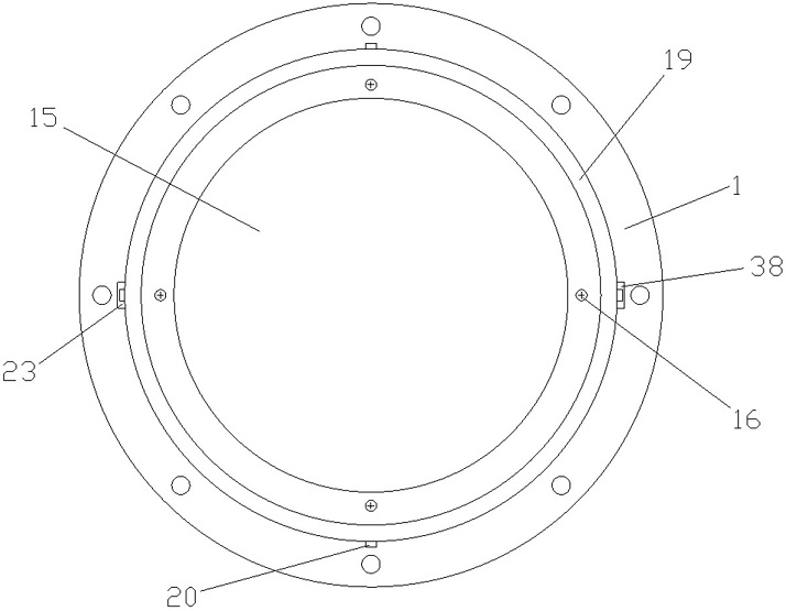
[0030] Such as Figure 1~8 As shown, the present invention provides an LED packaging structure, which includes a base 1, a limiting side 2 is provided on the edge of the surface of the base 1, and a housing 3 is provided on the surface of the base 1 inside the limiting side 2. The inner side of the bottom end of the shell 3 is provided with a first matching groove, the edge of the first matching groove is provided with a first expansion rubber ring 4, and the surface of the base 1 inside the first expansion rubber ring 4 is provided with a heat dissipation substrate 5 , the inner wall of the top of the housing 3 is provided with a second matching groove, the bottom end of the second matching groove is fitted with a gasket block 6, a lampshade 7 is arranged above the gasket block 6, and the gasket block 6 The inner side is provided with an annular third matching groove, and a rotating fixed seat 8 is fitted in the third matching groove, and a rotation control mechanism is arran...


PUM


Abstract

The invention discloses an LED packaging structure. The LED packaging structure comprises a base, wherein a shell is arranged on the surface, located on the inner side of a limiting edge, of the base; a heat dissipation substrate is arranged on the surface, located on the inner side of a first expansion rubber ring, of the base; a lampshade is arranged above a gasket block; a rotary fixing base is arranged in a third matching groove in a matched mode; a rotation control mechanism is arranged on the rotary fixing base and one side wall face of the shell; reflection cups are arranged in the fourth matching groove in a matched mode; an LED chip installation plate is arranged on the reflection cup located at the bottom of the groove; a combined lens is arranged on the reflection cup located above the LED chip installation plate; angle adjusting mechanisms are arranged at the bottom ends of the reflection cups and one side wall face of the shell; and an anti-dazzle net is arranged on the top surface of the lampshade. According to the LED packaging structure, mounting and fixing effects among the base, the shell, the lampshade and the anti-dazzle net are good, and light irradiation angles can be adjusted through the rotation control mechanism and the angle adjusting mechanisms. The invention further provides an LED light source device with sealing performance and light irradiation effect.

Description

technical field [0001] The invention relates to the technical field of LED lamps, in particular to an LED packaging structure and an LED light source device. Background technique [0002] The package structure mainly focuses on the form and category of the package, the material of the substrate, the shell, and the leads, emphasizing its important role in protecting the chip, enhancing the electrothermal performance, and facilitating the assembly of the whole machine. However, most of the existing LED package structures are in pursuit of higher sealing. Performance, the outer structure such as the bottom plate, the shell and the lampshade are sealed by integral molding, welding or sealant. Although the sealing performance of the LED lamp is improved, the operation difficulty will increase when the LED lamp needs to replace parts; moreover, large Most LED lamps still have defects in the aspect of internally adjusting the direction of light irradiation; therefore, it is necessa...

Claims


Application Information

Patent Timeline
Patent Type & Authority Applications(China)
IPC IPC(8): F21K9/20F21V5/04F21V15/00F21V17/16F21V31/00F21Y115/10
CPCF21V5/04F21V15/00F21V17/16F21V31/005F21K9/20F21Y2115/10
Inventor 魏俊敏
Owner 佛山市其利照明电器有限公司
Learn More