Soil-rock contact surface mechanical barrel-shaped shear tester combined with 3D printing technology

A 3D printing and shear test technology, applied in the direction of using a stable shear force to test the strength of materials, scientific instruments, instruments, etc., can solve the problems of difficult to obtain residual strength, correction of test data, reduction of shear area, etc. Achieve the effect of avoiding size effect, ensuring constant, and ensuring shear area

Active Publication Date: 2021-08-06
POWERCHINA HUADONG ENG COPORATION LTD
View PDF0 Cites 0 Cited by
  • Summary
  • Abstract
  • Description
  • Claims
  • Application Information

AI Technical Summary

Problems solved by technology

However, there are also the following defects: (1) only one-way short-displacement shearing can be performed, which is often used to obtain peak strength, but it is difficult to obtain residual strength; (2) the shear area continues to decrease during the test, and the test data needs fix
However, it is still rare to use the combination of 3D laser scanning technology and 3D printing technology to carry out physical shaping of rock mass structural surfaces, as well as application and physical test research.
And there is no 3D shaping concept based on the point cloud data of the planar structural surface for equal-proportion barrel-shaped structural surface

Method used


Image

  • Soil-rock contact surface mechanical barrel-shaped shear tester combined with 3D printing technology
  • Soil-rock contact surface mechanical barrel-shaped shear tester combined with 3D printing technology
  • Soil-rock contact surface mechanical barrel-shaped shear tester combined with 3D printing technology

Examples


Embodiment Construction

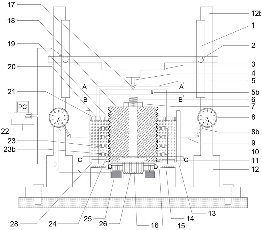
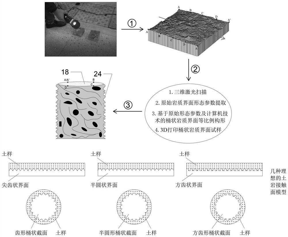
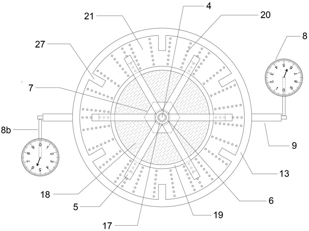
[0040]This embodiment is a barrel-shaped shear tester for soil-rock contact surface mechanics combined with 3D printing technology, which mainly includes a frame, a rock sample fixing mechanism, a shear box 13, an axial pressure mechanism, a rotary drive mechanism, and a shear monitoring mechanism. Mechanism and computer 22 for performing shear mechanics test using the barrel-shaped rock sample 18 and the ring-shaped soil sample 10 formed around the barrel-shaped rock sample 18 and in contact with the outer interface of the barrel-shaped rock sample 18, wherein the barrel-shaped rock sample 18 The outer rock interface 24 is formed from the point cloud data obtained by three-dimensional laser scanning of the natural rock interface through coordinate transformation and equal-scale configuration, and then combined with 3D printing technology, the barrel-shaped rock sample 18 and its outer rock interface 24 and print.

[0041] In this example, the rock sample fixing mechanism has ...


PUM


Abstract

The invention relates to a soil-rock contact surface mechanical barrel-shaped shear tester combined with a 3D printing technology, which is used for carrying out a soil-rock contact surface mechanical shear test by utilizing a barrel-shaped rock sample and an annular soil sample which is formed around the barrel-shaped rock sample and is in contact with a rock interface on the outer side of the barrel-shaped rock sample. The soil-rock contact surface mechanical barrel-shaped shear tester includes: a frame; a rock sample fixing mechanism which is used for fixing the barrel-shaped rock sample; a shear box, wherein the shear box is provided with a shear box bottom plate corresponding to the bottom surface of the annular soil sample and a shear box outer cover corresponding to the outer side surface of the annular soil sample, the shear box bottom plate and the shear box outer cover are connected into a whole, and the bottom surface of the shear box bottom plate can be mounted on the frame in a manner of rotating around the axis of the shear box; an axial pressurizing mechanism which is positioned above the annular soil sample and is used for applying axial pressure to the annular soil sample; a rotary driving mechanism which is connected to the rock sample fixing mechanism and is used for driving the barrel-shaped rock sample to rotate around the axis of the barrel-shaped rock sample through the rock sample fixing mechanism; and a shearing monitoring mechanism which is used for collecting shearing parameters between the rock interface on the outer side of the barrel-shaped rock sample and the annular soil sample.

Description

technical field [0001] The invention relates to a barrel shear tester for soil-rock contact surface mechanics combined with 3D printing technology. The utility model is applicable to the technical field of rock-soil contact surface mechanics test. Background technique [0002] The direct shear instrument is not only a commonly used test instrument for the study of the shear properties of soil, but also often used for the study of the mechanical properties of the soil-rock contact surface. The advantages of this instrument are: (1) The shape condition of the shear displacement surface is clear; (2) The mechanical loading condition is simple and clear; (3) The test steps and process are relatively simple. However, there are also the following defects: (1) only one-way short-displacement shearing can be performed, which is often used to obtain peak strength, but it is difficult to obtain residual strength; (2) the shear area continues to decrease during the test, and the test ...

Claims


Application Information

Patent Timeline
IPC IPC(8): G01N3/24G01N3/02
CPCG01N3/24G01N3/02
Inventor 范志强周奇辉张琼方汪明元倪卫达黄待望刘尊景楼永良
Owner POWERCHINA HUADONG ENG COPORATION LTD
Why Eureka
Try Eureka