Novel high-storage-rate VHF antenna
A new type of storage rate technology, applied to antennas, folded antennas, antenna components and other directions, can solve the problems of ineffective loading, large size and weight, low deployment fundamental frequency, etc., to achieve high application promotion value, high storage rate, and prevent The effect of overshoot
- Summary
- Abstract
- Description
- Claims
- Application Information
AI Technical Summary
Problems solved by technology
Method used
Image
Examples
Embodiment 1
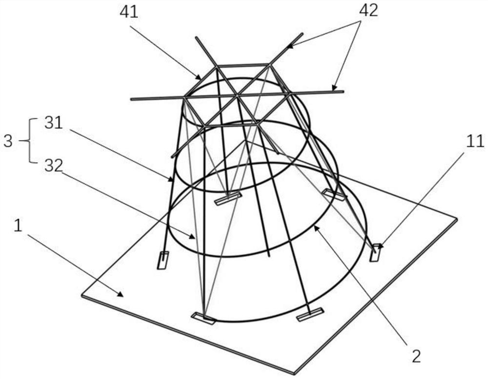
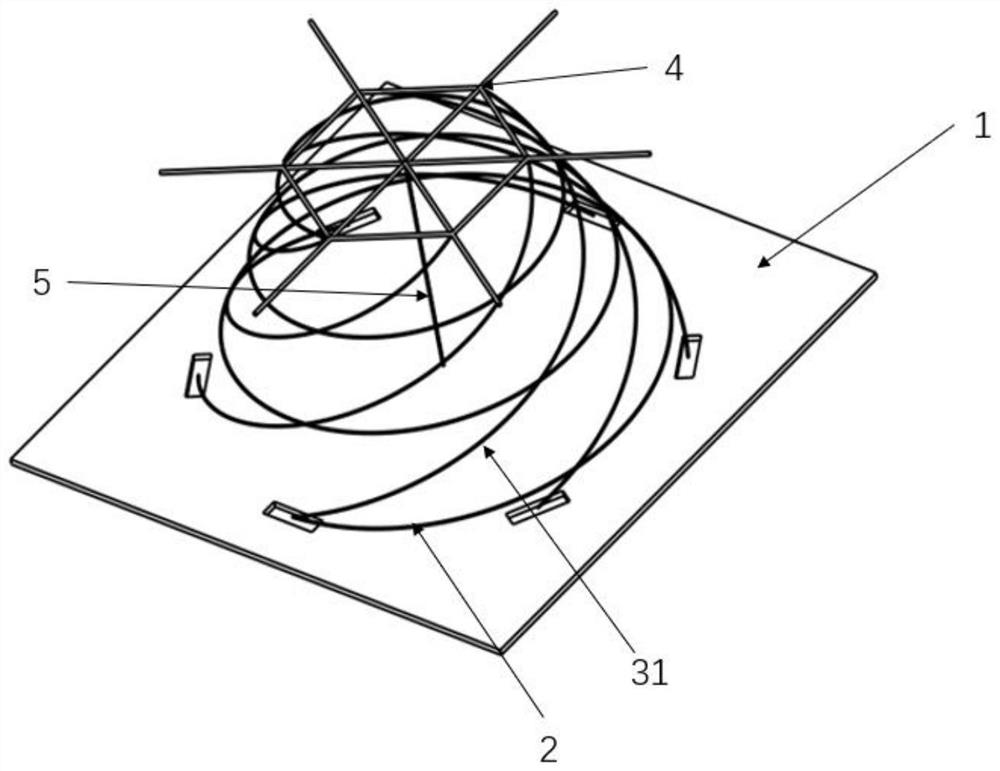
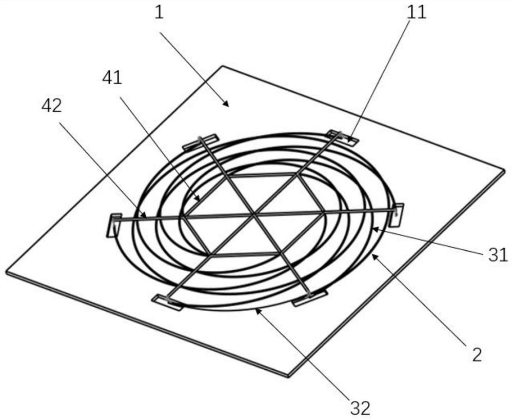
[0028] The present invention provides a novel VHF antenna with high storage rate, which includes a base 1 , an antenna radiation arm 2 installed on the base 1 , a self-deploying device 3 , and a supporting device 4 connected with the self-deploying device 3 . The base 1 provides a mounting platform for the antenna, and the base 1 is provided with a crimping groove 11 connecting the antenna radiating arm 2 and the self-deploying device 3. The structure matches the setting. Preferably, the base 1 adopts a metal skin-honeycomb structure, which can simultaneously have two functions of antenna electrical reflection and structural support. The antenna radiating arm 2 is made of elastic metal material, such as beryllium bronze, etc., and can be cylindrical or conical spiral according to the electrical index of the antenna. The self-expanding device 3 includes a plurality of elastic rods 31 made of non-metallic material, and the number of the elastic rods 31 is greater than or equal ...
Embodiment 2
[0032] This embodiment 2 is formed on the basis of embodiment 1. Through the optimized design of the structure of the support device, the structural strength of the support device is improved, and at the same time, the support device can also have a locking function, and the self-expanding device after the disk is pressed and the The antenna is locked in the retracted state, which further simplifies the structure of the device and improves work efficiency. specifically:
[0033] The support device 4 is also provided with a support shaft 42 , and the two ends of the support shaft 42 are respectively connected to the support ring 41 to strengthen the structural strength of the support ring 41 . Preferably, a plurality of support shafts 42 are connected to the support ring 41 , and the plurality of support shafts 42 cross each other to form a network structure or the plurality of support shafts 42 intersect at the inner center of the support ring 41 to form a car wheel-like struc...
Embodiment 3
[0037] This embodiment 3 is formed on the basis of embodiment 1 or embodiment 2. The structural strength of the self-deploying device is improved by optimizing the structure of the self-deploying device. The impact phenomenon reduces the impact of the antenna deployment on the star. specifically:
[0038] The self-expanding device 3 is also provided with a flexible support wire 32, the flexible support wire 32 can be a Kevlar fiber rope, and its flexible support wire 32 is connected between two adjacent elastic rods 31 in a diagonally pulled manner. 31 deformation and deformation. Preferably, both ends of the flexible support wire 32 are respectively connected to the top and bottom ends of two adjacent elastic rods 31, so that the quadrilateral formed by the two elastic rods 31 is changed into two triangles. The flexible support wire 32 effectively improves the structural strength of the cylindrical structure formed by the self-deploying device 3 and ensures the stiffness of...
PUM
 Abstract
Description
Claims
Application Information
 - R&D
- Intellectual Property
- Life Sciences
- Materials
- Tech Scout
- Unparalleled Data Quality
- Higher Quality Content
- 60% Fewer Hallucinations
Browse by: Latest US Patents, China's latest patents, Technical Efficacy Thesaurus, Application Domain, Technology Topic, Popular Technical Reports.
© 2025 PatSnap. All rights reserved.Legal|Privacy policy|Modern Slavery Act Transparency Statement|Sitemap|About US| Contact US: help@patsnap.com


