Non-destructive coating equipment for electric vehicle parts production
A technology for electric vehicles and accessories, applied in the direction of coating, pretreatment surface, spray booth, etc., can solve the problems of uneven and comprehensive application of paint, low degree of automatic production, low processing efficiency, etc., to save labor, speed up and Efficiency, the effect of improving processing efficiency
- Summary
- Abstract
- Description
- Claims
- Application Information
AI Technical Summary
Problems solved by technology
Method used
Image

Examples
Embodiment 1
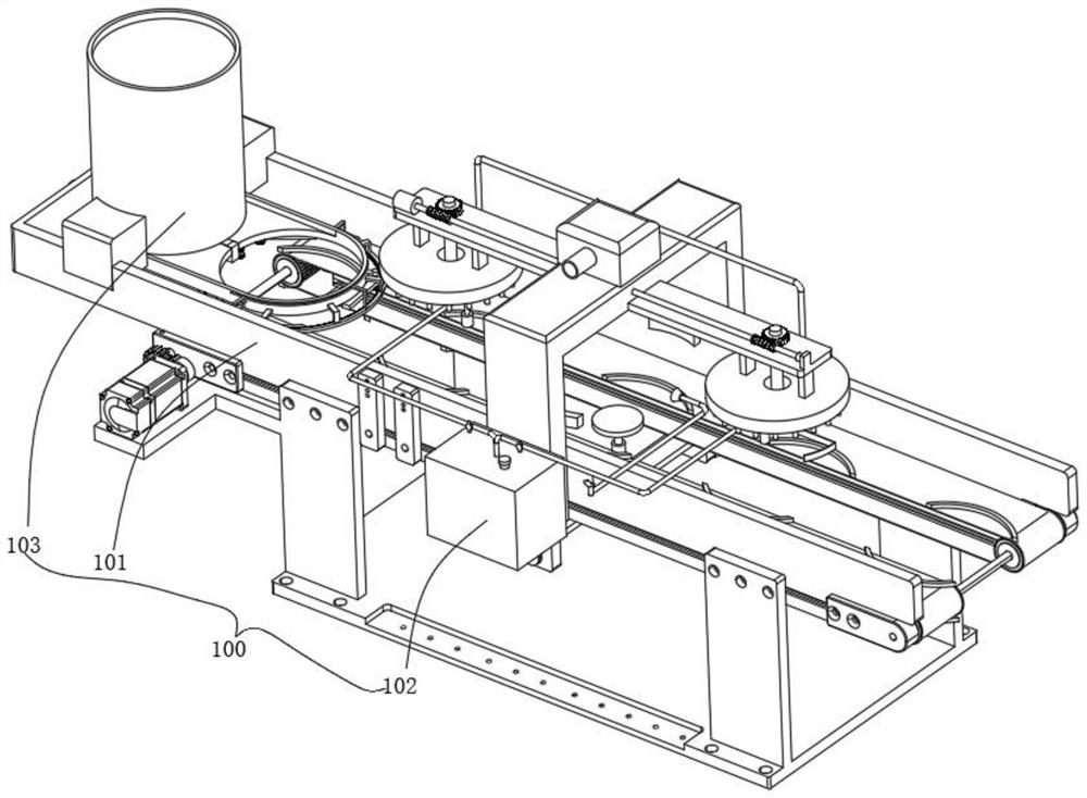
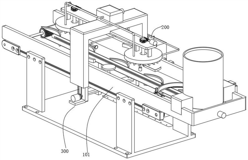
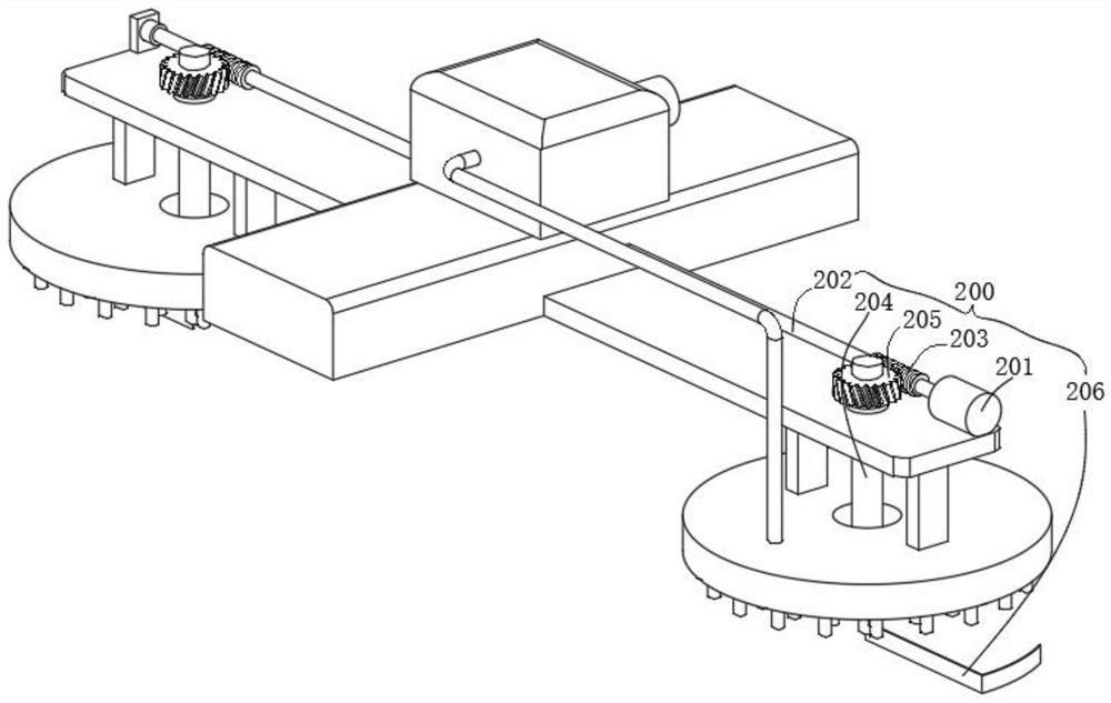
[0051] combine figure 1 , 2 , 3 and 5, the non-destructive coating equipment for the production of electric vehicle parts provided by the present invention includes a body 100, a smearing mechanism 200, a turning mechanism 300, a drying mechanism 400, a blanking mechanism 500 and a transmission mechanism 600, and the body 100 includes a support Frame 101, the storage barrel 103 fixed on the support frame 101 and the spraying assembly arranged on one side of the support frame 101, the smearing mechanism 200 includes a first motor 201 fixed on the support frame 101, a first motor 201 fixed on the first motor The power transmission shaft 202 at the output end of 201, the worm screw 203 that is sleeved on both sides on the transmission shaft 202, the first electric telescopic rod 204 that is rotatably installed on both sides on the support frame 101, is sleeved on the first electric telescopic rod 204 and is connected with the worm screw 203 The worm wheel 205 for meshing transmi...
Embodiment 2
[0055] combine figure 2 with 4 As shown, on the basis of Embodiment 1, the turning mechanism 300 includes a second motor 301 fixed on the support frame 101, a connecting shaft 302 fixed on the output end of the second motor 301, and sleeves on both sides of the connecting shaft 302. The first pulley, the second electric telescopic rod 303 that is rotatably installed on both sides of the support frame 101, the second pulley that is sleeved on the second electric telescopic rod 303 and is connected to the first pulley through a belt, is fixed to the second electric telescopic rod 303 The block 304 at the end of the telescopic rod 303, the electric push rod 306 arranged at the bottom of the support frame 101, and the electromagnet 307 affixed to the end of the electric push rod 306, the electromagnet 307 starts and uses magnetic force to fix the accessories, and the electric push rod 306 starts to push the electromagnet 307 to rise, and the accessories rise with the electromagn...
Embodiment 3
[0058] combine figure 2 with 6 As shown, in the above embodiment, the drying mechanism 400 includes a dryer 401 fixed on the support frame 101, an air deflector 402 fixed on both sides of the support frame 101, and a bottom of the air deflector 402. A plurality of conveying pipes 403, the dryer 401 communicates with the air guide plate 402 through the air pipe, the dryer 401 is started, and the hot air is transported into the air guide plate 402 through the air pipe, and then the air is transported from the air guide plate 402 The pipe 403 is discharged, and then the paint on the accessories can be dried, which can speed up the speed and efficiency of the coating, and can avoid damage to the painted side when turning over.
PUM
 Abstract
Description
Claims
Application Information
 - R&D
- Intellectual Property
- Life Sciences
- Materials
- Tech Scout
- Unparalleled Data Quality
- Higher Quality Content
- 60% Fewer Hallucinations
Browse by: Latest US Patents, China's latest patents, Technical Efficacy Thesaurus, Application Domain, Technology Topic, Popular Technical Reports.
© 2025 PatSnap. All rights reserved.Legal|Privacy policy|Modern Slavery Act Transparency Statement|Sitemap|About US| Contact US: help@patsnap.com