Tool setting detection method for machine tool
A detection method and machine tool technology, applied in the direction of measuring/indicating equipment, metal processing machinery parts, automatic control devices, etc., can solve the problems of increased operation interference collision risk, unfavorable delivery efficiency, and improvement, so as to improve the detection speed of tool setting, Realize high-precision adjustment and improve the effect of risk management and control
- Summary
- Abstract
- Description
- Claims
- Application Information
AI Technical Summary
Problems solved by technology
Method used
Image
Examples
Embodiment 1
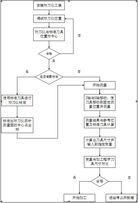
[0051] This embodiment discloses a tool setting detection method for a machine tool, as a basic implementation of the present invention, including the installation of the tool setting instrument 2, pre-test preparation, tool setting calibration and tool setting measurement;
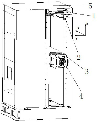
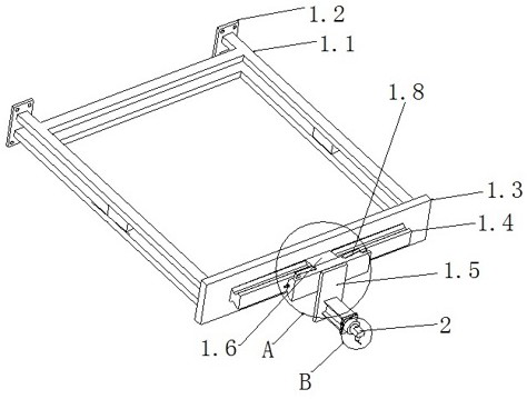
[0052] For the installation of the tool setting instrument 2, set up a special tool setting instrument 2 tooling, install the tool setting instrument 2 on the machine column 5 through the tool setting instrument 2 tooling, and adjust the position of the tool setting instrument 2 by adjusting the tool setting instrument 2 tooling , so that the tool setting instrument 2 is at the detection station;
[0053] Pre-test preparations, install the standard tool 4 on the spindle of the CNC machine tool, adjust the attitude of the CNC machine tool and the tool setting instrument 2 based on the manual mode of the CNC machine tool, and record the alignment of the standard tool 4 in the three-dimensional coordinate sys...
Embodiment 2
[0058] This embodiment discloses a machine tool tool setting detection method, as a preferred embodiment of the present invention, that is, in embodiment 1, the pre-detection preparation includes the following steps:
[0059] S11, establish a three-dimensional coordinate system of the workpiece based on the control system of the CNC machine tool, and make the X-axis of the three-dimensional coordinate system of the workpiece correspond to the direction of expansion and contraction of the ram 3 of the CNC machine tool, and the Z-axis of the three-dimensional coordinate system of the workpiece correspond to the vertical movement direction of the ram 3 of the CNC machine tool , The Y-axis of the three-dimensional coordinate system of the workpiece corresponds to the direction in which the bed of the CNC machine tool moves;
[0060] S12: Based on the control system of the CNC machine tool, set the safety area protection for the tool setting instrument 2 in the manual mode of the CN...
Embodiment 3
[0067] This embodiment discloses a tool setting detection method for a machine tool. As a preferred embodiment of the present invention, that is, in Example 2, the tool setting calibration includes the following steps:
[0068] S21, establishing a three-dimensional coordinate system of the machine tool based on the control system of the CNC machine tool;
[0069] S22, based on the control system of the CNC machine tool, the tool calibration program is compiled, the coordinate value A and the coordinate value B are input into the calibration program, and the tool number of the standard tool 4 is input into the calibration program at the same time, so as to call the standard tool in the tool compensation parameter 4 dimensions;
[0070] S23, run the calibration program to move the tool to be tested to the position corresponding to the coordinate value A, then control the expansion and contraction of the ram 3, so that the standard tool 4 touches the tool setting instrument 2 in ...
PUM
 Abstract
Description
Claims
Application Information
 - R&D
- Intellectual Property
- Life Sciences
- Materials
- Tech Scout
- Unparalleled Data Quality
- Higher Quality Content
- 60% Fewer Hallucinations
Browse by: Latest US Patents, China's latest patents, Technical Efficacy Thesaurus, Application Domain, Technology Topic, Popular Technical Reports.
© 2025 PatSnap. All rights reserved.Legal|Privacy policy|Modern Slavery Act Transparency Statement|Sitemap|About US| Contact US: help@patsnap.com


