Reinforced cement movable mobile house

A technology of reinforced concrete and movable houses, which is applied to residential buildings, building components, and fire prevention. It can solve the problems of poor overall solidity and durability, limited security and anti-theft performance, and large impact of external forces. performance, the effect of avoiding displacement

Pending Publication Date: 2021-08-10
佛山市乐居科技有限公司
View PDF3 Cites 0 Cited by
  • Summary
  • Abstract
  • Description
  • Claims
  • Application Information

AI Technical Summary

Problems solved by technology

[0003] When the existing prefabricated houses for construction sites are used on the construction ground, foundation treatment needs to be carried out on the placement point, and the disaster resistance is not strong. Due to the influence of the installation

Method used


Image

  • Reinforced cement movable mobile house
  • Reinforced cement movable mobile house
  • Reinforced cement movable mobile house

Examples


Embodiment 1

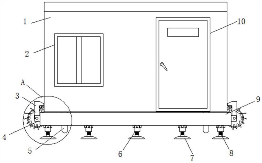
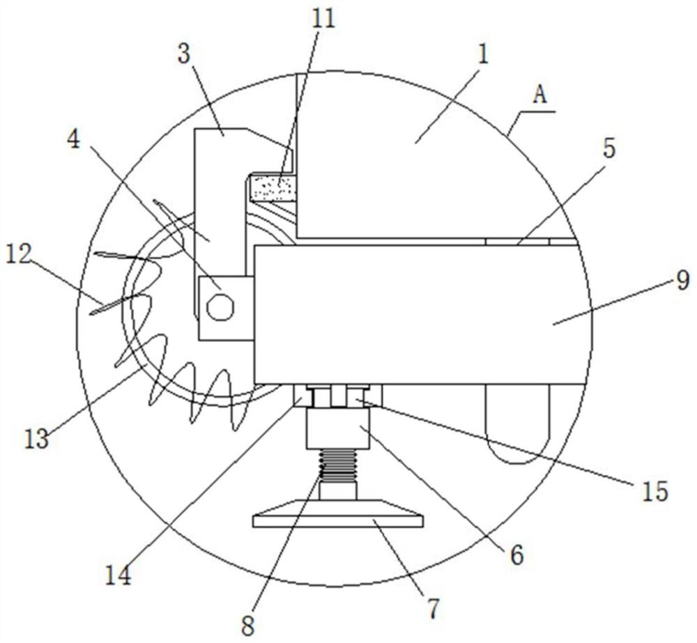
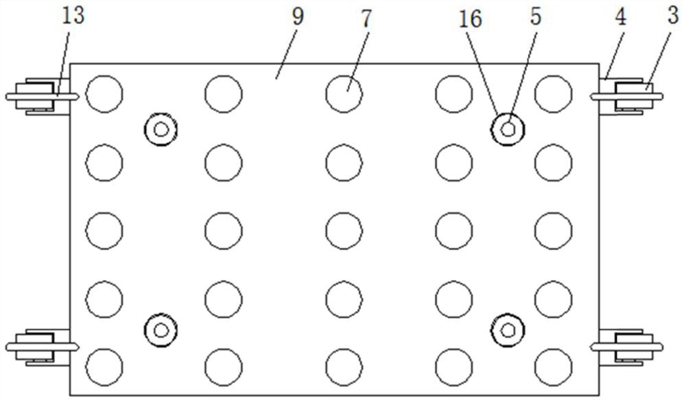
[0023] see Figure 1 to Figure 4 , the present invention provides a technical solution: a reinforced concrete movable house, including a house body 1, a bottom plate 9 is provided at the bottom of the house body 1, and mounting frames 4 are fixed at the four corners of the side walls of the bottom plate 9. Blocks 11 are fixed at the four corners of the side wall of the body 1, and the inside of the installation frame 4 is connected to the frame 3 through the rotation of the shaft column. Through the design of the frame 3 and the block 11, the frame 3 is stuck on the block by rotating one end 11 is clamped and connected, so as to realize fast assembly and fixation between the room body 1 and the bottom plate 9, which greatly reduces the difficulty of assembly. One end of the card frame 3 is placed on the top of the block 11, and the bottom end of the bottom plate 9 is provided with a rotary cylinder 6. Through The designed rotary drum 6 and screw rod 8, rotating the rotary drum...

Embodiment 2

[0027] see Figure 1 to Figure 4 , the present invention provides a technical solution: a reinforced concrete movable house, including a house body 1, a bottom plate 9 is provided at the bottom of the house body 1, and mounting frames 4 are fixed at the four corners of the side walls of the bottom plate 9. Blocks 11 are fixed at the four corners of the side wall of the body 1, and the inside of the installation frame 4 is connected to the frame 3 through the rotation of the shaft column. Through the design of the frame 3 and the block 11, the frame 3 is stuck on the block by rotating one end 11 is clamped and connected, so as to realize fast assembly and fixation between the room body 1 and the bottom plate 9, which greatly reduces the difficulty of assembly. One end of the card frame 3 is placed on the top of the block 11, and the bottom end of the bottom plate 9 is provided with a rotary cylinder 6. Through The designed rotary drum 6 and screw rod 8, rotating the rotary drum...


PUM


Abstract

The invention discloses a reinforced concrete movable mobile house. The reinforced concrete movable mobile house comprises a house body, a bottom plate is arranged at the bottom end of the house body, mounting frames are fixed to the four corners of the side wall of the bottom plate, clamping blocks are fixed to the four corners of the side wall of the house body, clamping frames are rotatably connected to the interiors of the mounting frames through shaft columns, one ends of the clamping frames are arranged at the tops of the clamping blocks, a rotating cylinder is arranged at the bottom end of the bottom plate, a screw rod is connected to the inner side of the rotating cylinder through threads, and a base is fixed to the bottom end of the screw rod. According to the reinforced concrete movable mobile house, by designing the clamping frames and the clamping blocks, the clamping frames are clamped on the clamping blocks by rotating one ends to be fixedly connected in a clamping manner, so that the room body and the bottom plate are quickly assembled and fixed, and the assembling difficulty is greatly reduced; and by designing the rotating cylinder and the screw rod, the rotating cylinder is rotated to drive the screw rod to perform thread screwing adjustment, and therefore, the horizontal height of the house can be adjusted, foundation treatment is not needed, the construction difficulty is greatly reduced, and the working time is shortened.

Description

technical field [0001] The invention belongs to the technical field of simple buildings, and in particular relates to a movable prefabricated house made of reinforced concrete. Background technique [0002] The temporary residences on the construction site are all made of movable houses. It is impossible and unnecessary to build permanent houses. There are many types of movable houses. Generally, metal profiles are used to make frames. The walls and ceilings are made of wood, plastic panels or canvas, and are directly installed On the ground, the movable room is easy to carry. [0003] When the existing prefabricated houses for construction sites are used on the construction ground, foundation treatment needs to be carried out on the placement point, and the disaster resistance is not strong. Due to the influence of installation methods, the overall solidity and durability are poor, and it is greatly affected by external wind, rain, lightning and external force impacts, and...

Claims


Application Information

Patent Timeline
IPC IPC(8): E04H1/02E04B1/343E04B1/38E04B1/94
CPCE04H1/02E04B1/343E04B1/38E04B1/94
Inventor 罗泽定
Owner 佛山市乐居科技有限公司
Why Eureka
Try Eureka