
Optimized wind turbine blade deicing method

A wind turbine blade and blade technology, which is applied in the field of optimized wind turbine blade deicing, can solve the problems of reduced blade aerodynamic performance, increased force on the wind turbine suspension mechanism, and increased wind turbine weight, etc., so as to improve economic benefits and reduce energy consumption. consumption effect

Active Publication Date: 2021-08-10
LOW SPEED AERODYNAMIC INST OF CHINESE AERODYNAMIC RES & DEV CENT
View PDF16 Cites 0 Cited by
  • Summary
  • Abstract
  • Description
  • Claims
  • Application Information

AI Technical Summary

Problems solved by technology

However, in cold climate regions, the reduction of aerodynamic performance of wind turbine blades due to icing, additional vibration of wind rotors, failure of control strategies, threat of ice shedding, etc. have become the core bottlenecks that limit the utilization of wind energy in cold climates.
[0003] There are many problems in the long-term freezing of the blades of the wind turbine: the ice of the blades increases the weight of the wind turbine, increases the force on the suspension mechanism of the wind turbine, and at the same time affects the shape of the blades, increases the rotational resistance, and greatly reduces the wind turbine power generation efficiency
Generally, it will affect the power generation of wind turbines and wind farms, and increase the power consumption of the wind farms, affecting the economic benefits of wind farms

Method used


Image

  • Optimized wind turbine blade deicing method
  • Optimized wind turbine blade deicing method
  • Optimized wind turbine blade deicing method

Examples


Embodiment Construction

[0039] The following description provides many different embodiments, or examples, for implementing various features of the invention. The elements and arrangements described in the following specific examples are only used to express the present invention in a concise manner, and are only used as examples rather than limiting the present invention.

[0040] An optimized wind turbine blade deicing method, comprising the following steps:

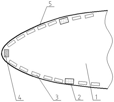
[0041] S10. The wind turbine blade 1 is divided into regions, divided into high-power continuous heating zone, low-power continuous heating zone and periodic heating zone; correspondingly, a high-power continuous electric heating unit 4 is set in the high-power continuous heating zone, A low-power continuous electric heating unit 2 is set in the power continuous heating area, and a periodic electric heating unit 3 is set in the periodic heating area;

[0042] Such as figure 1 As shown, the high-power continuous heating zone is located at th...


PUM


Abstract

The invention belongs to the field of wind turbine blade ice prevention and removal, and particularly relates to an optimized wind turbine blade deicing method. The optimized wind turbine blade deicing method comprises the following steps that a wind turbine blade is divided into a high / low-power continuous heating area and a periodic heating area; the required current heat is calculated by setting the initial value of the surface temperature of the blade; the current heat rate is adopted for testing, the current heat rate value is adjusted, and the optimal electric heat flow rate needed by the low / high-power continuous heating area is obtained; the accumulated ice shape of the periodic heating area is obtained through tests of the two optimal values, the icing resultant force is obtained through simulation calculation according to the accumulated ice shape, the icing adhesion force is made to be equal to the icing resultant force, the surface temperature of the periodic heating area is obtained through calculation, and then the electric heating flow rate needed by the periodic heating area is obtained; and finally, the optimal heat flow rate values, obtained through tests and simulation, of all the areas are used for controlling all the areas for deicing. According to the optimized wind turbine blade deicing method, energy consumption can be reduced on the basis of effective deicing, and economic benefits of a wind power plant can be improved.

Description

technical field [0001] The invention relates to the field of anti-icing and deicing of wind turbine blades, in particular to an optimized wind turbine blade deicing method. Background technique [0002] In recent years, with the rapid development of the wind power market, the utilization of wind energy resources in cold climates has received more and more attention. However, in cold climate regions, the reduction of aerodynamic performance of wind turbine blades due to icing, additional vibration of wind rotors, failure of control strategies, threat of ice shedding, etc. have become the core bottlenecks that limit the utilization of wind energy in cold climates. [0003] There are many problems in the long-term freezing of the blades of the wind turbine: the ice of the blades increases the weight of the wind turbine, increases the force on the suspension mechanism of the wind turbine, and at the same time affects the shape of the blades, increases the rotational resistance, ...

Claims


Application Information

Patent Timeline
Patent Type & Authority Applications(China)
IPC IPC(8): F03D80/40F03D80/60F03D1/06
CPCF03D1/0675F03D80/40F03D80/60Y02E10/72
Inventor 周靓王强易贤白云卯石雅楠刘宇
Owner LOW SPEED AERODYNAMIC INST OF CHINESE AERODYNAMIC RES & DEV CENT
Learn More