Pump body mounting structure for container type sewage treatment equipment

A kind of sewage treatment equipment, container-type technology, applied in the direction of water/sewage treatment, water/sludge/sewage treatment, components of pumping devices for elastic fluids, etc., can solve the problem of affecting the convenience of use, disassembly and assembly of power pumps Troublesome, troublesome reinstallation and other problems, to achieve the effect of improving convenience, improving the convenience of disassembly and maintenance, and improving the convenience of operation and use

Active Publication Date: 2021-08-10
XIAMEN JIARONG TECH CO LTD
View PDF8 Cites 0 Cited by
  • Summary
  • Abstract
  • Description
  • Claims
  • Application Information

AI Technical Summary

Problems solved by technology

[0003] In the prior art, the sewage transport in the container is usually powered by a power pump, and the power pump is directly fixed in the container body with bolts. However, when in use, the power pump has a long life, and the power pump needs to be adjusted according to the on-site working conditions after the container is transported. The position in the box is fixed by bolts, which makes the disassembly and assembly of the power pump more troublesome, and when the position is transferred, it is more troublesome to disassemble and then reinstall, which affects the convenience of use

Method used


Image

  • Pump body mounting structure for container type sewage treatment equipment
  • Pump body mounting structure for container type sewage treatment equipment
  • Pump body mounting structure for container type sewage treatment equipment

Examples


Embodiment Construction

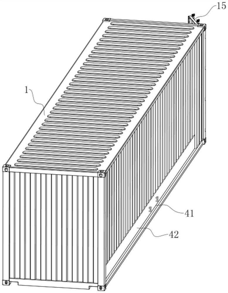
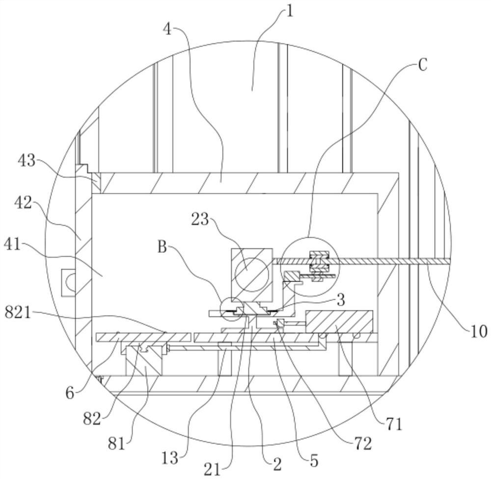
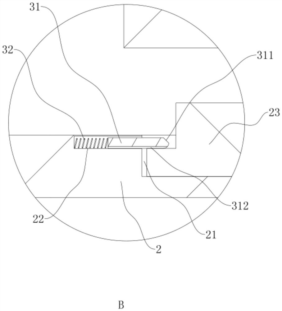
[0032] refer to Figure 1 to Figure 6 The installation structure of the pump body of the container-type sewage treatment equipment is further explained.

[0033] A pump body installation structure of container type sewage treatment equipment, such as figure 1 and figure 2 As shown, it includes a container body 1 and several pump body seats 2 located on the container body 1. One end of the container body is provided with a container door 15, which is convenient for entering into the container body for operation, and a pump body 23 is arranged on the pump body seat 2. The placement groove 21, the pump body 23 is placed in the placement groove 21 of the pump body 23, and the elastic clamping piece 3 for clamping or loosening the pump body 23 is arranged on the pump body seat 2, so as to facilitate the disassembly and assembly of the pump body 23 When transferring the pump body 23, the pump body 23 can be directly transferred by transferring the pump body seat 2, or the pump bo...


PUM


Abstract

The invention discloses a pump body mounting structure for container type sewage treatment equipment, and relates to the technical field of sewage treatment. The pump body mounting structure for the container type sewage treatment equipment is characterized by comprising a container body and a plurality of pump body bases, placing grooves are formed in the pump body bases, a conveying interlayer is arranged on the container body, a pump body mounting table and a moving table are arranged in the conveying interlayer, a transferring mechanism is arranged on the pump body mounting table, a moving mechanism is arranged on the moving table, the multiple pieces of sewage treatment equipment are arranged in the container body, conveying pipe joints are arranged at the water inlet ends and the water outlet ends of the sewage treatment equipment, the ends, away from the sewage treatment equipment, of the conveying pipe joints penetrate into the conveying interlayer, pipeline joints are arranged on the pump body bases, and pipe connecting mechanisms are arranged at one ends of the pipeline joints. The pump body mounting structure has the advantages that the pump body can be conveniently arranged and transferred for use, disassembly, assembly and maintenance are convenient, and the effect of improving the use convenience of the pump body can be achieved.

Description

technical field [0001] The invention relates to the technical field of sewage treatment, more specifically, it relates to a pump body installation structure of container-type sewage treatment equipment. Background technique [0002] With the advocacy of environmental protection, the treatment of sewage has become a key development direction of environmental protection. There are many container-type sewage treatment equipment on the market for treating RO concentrated water and making it produce water. This type of container-type sewage treatment equipment integrates all treatment equipment into the container, which not only occupies a small area and is easy to manage, but also The operation is convenient, and the concentrated water can be treated into produced water, so as to improve the recycling rate of raw water. [0003] In the prior art, the sewage transport in the container is usually powered by a power pump, and the power pump is directly fixed in the container body ...

Claims


Application Information

Patent Timeline
IPC IPC(8): F16M1/00F04B53/16F04B53/22C02F1/00
CPCF16M1/00F04B53/16F04B53/22C02F1/00
Inventor 刘德灿梁博文温联河方艺民叶杜平
Owner XIAMEN JIARONG TECH CO LTD
Why Eureka
Try Eureka