Ceiling lamp mounting bracket and ceiling lamp

A technology for installing brackets and dome lights, which is applied to lampshades, lighting devices, transportation and packaging, etc. It can solve the problems of low safety and difficult installation and operation, and achieve the effects of maintaining internal cleanliness, convenient disassembly and assembly, and simple structure

Inactive Publication Date: 2021-08-10
YANYANG LAMP SET TIANCHANG CITY
View PDF3 Cites 0 Cited by
  • Summary
  • Abstract
  • Description
  • Claims
  • Application Information

AI Technical Summary

Problems solved by technology

However, compared with navigation lights, cabin dome lights generally adopt a hanging installation method, which needs to be installed on a high shelf during installation, which is difficult to install and has low safety.

Method used


Image

  • Ceiling lamp mounting bracket and ceiling lamp
  • Ceiling lamp mounting bracket and ceiling lamp
  • Ceiling lamp mounting bracket and ceiling lamp

Examples


Embodiment 1

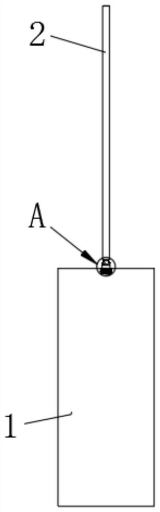
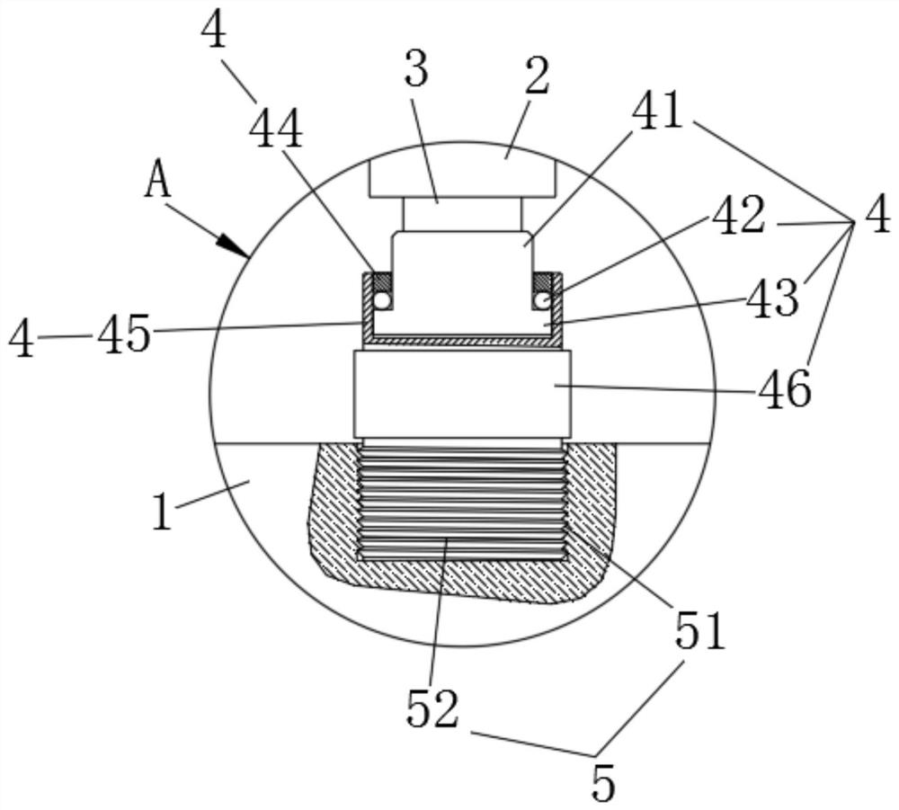
[0040] Such as figure 1 and figure 2 As shown, the present invention provides a dome light installation bracket, which includes a dome light body 1 , a structural pipe 2 , a sling 3 , a rotating structure 4 and a locking structure 5 . The rotating structure 4 includes a connecting block 41 , a ball 42 , a protrusion 43 , a block 44 and a connecting sleeve 45 . The interior of the structural pipe 2 runs through the suspension rope 3 along the axial direction. A connecting block 41 is adhered to the bottom end of the suspension rope 3 . The bottom end of the connection block 41 is embedded in the connection sleeve 45 , and a protrusion 43 extends outward from the outside of the connection block 41 close to the bottom end. A block 44 is disposed above the protrusion 43 . The stopper 44 is integrally formed inside the opening top of the connecting sleeve 45 . A plurality of balls 42 are arranged between the stopper 44 and the protrusion 43 along the circumferential direction...

Embodiment 2

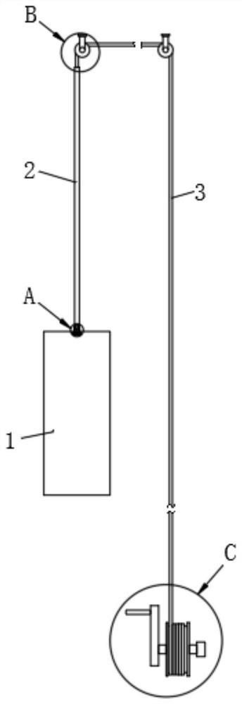
[0045] Such as image 3 and Figure 4 As shown, in this embodiment, on the basis of the above embodiments, the suspension rope 3 passes through the top of the structural pipe 2, and turns around two fixed pulleys 6 located on the same horizontal line in turn, and extends downward. One end of the suspension rope 3 extending downward is connected to the top surface of the dome light body 1 , and the other end is connected to the wire wheel assembly 7 .

[0046] preferred, see Figure 5 , in one of the preferred technical solutions of this embodiment, the wire wheel assembly 7 includes a wire take-up wheel 71 and a hand wheel 72 . The end portion of the suspension rope 3 is adhered to the wheel body of the take-up wheel 71 . The take-up pulley 71 is connected to the handwheel 72 through a rotating shaft transmission along the central axis.

[0047] Preferably, in one of the preferred technical solutions of this embodiment, turning the hand wheel 72 drives the take-up wheel 71...

Embodiment 3

[0049] Such as Figure 6 As shown, in this embodiment, on the basis of the above embodiments, the interior of the dome light body 1 is fixedly connected with a lamp tube 11 by bolts. The bottom of the dome light body 1 is open. And the outside of the bottom end of the dome light body 1 is provided with external threads. And the outside of the bottom end of the dome light body 1 is connected with a baffle shell 81 through an external thread. The blocking shell 81 penetrates up and down, and its inner diameter is larger than the size of the bottom opening of the dome light body 1 . A glass cover 82 is adhered to the bottom inner wall of the shielding shell 81 .

[0050] In this embodiment, the glass cover 82 can be connected or separated from the dome light body 1 by rotating the cover 81, which is easy to disassemble; and by setting the glass cover 82, it can effectively prevent mosquitoes and sundries from entering the interior of the dome light body 1 , keep the internal ...


PUM


Abstract

The invention relates to the technical field of marine lamps, and particularly provides a ceiling lamp mounting bracket and a ceiling lamp. Theceiling lamp mounting bracket comprises a ceiling lamp body, a structural tube, a lifting rope, a rotating structure and a locking structure; a structural pipe is arranged over the ceiling lamp body; a lifting rope penetrates through the interior of the structural pipe in the axis direction; the bottom of the lifting rope is detachably connected with the ceiling lamp body through a locking structure; the lifting rope and the ceiling lamp body are connected or separated through the locking structure, mounting and dismounting of the ceiling lamp body are completed, and the ceiling lamp mounting bracket has the technical advantages of being simple in structure and convenient and fast to dismount and mount and is suitable for being used on a ship.

Description

technical field [0001] The invention relates to the technical field of marine lamps, in particular to a mounting bracket for a dome light and a dome light. Background technique [0002] The dome light is a light installed on the top of the ship or waiting room, mainly used to illuminate a large range of cabin environment, and it is characterized by high installation height, strong brightness and wide radiation range. The patent document with the patent number 202022602176.8 discloses a beacon light stand with adjustable height of the beacon light. The main body of the navigation light adjusts the upper and lower positions, thereby adjusting the use height of the navigation light, which solves the problem that the use height of the navigation light cannot be adjusted according to the environment, and improves the applicability of the navigation light. However, compared with navigation lights, cabin dome lights generally adopt a hanging installation method, which needs to be ...

Claims


Application Information

Patent Timeline
Patent Type & Authority Applications(China)
IPC IPC(8): F21S8/06F21V21/104F21V21/38F21V17/10F21V3/00F21V31/00B63B45/00F21W107/20
CPCF21S8/061F21V21/104F21V21/38F21V17/10F21V3/00F21V31/005B63B45/00F21W2107/20
Inventor 吴昊潘学元
Owner YANYANG LAMP SET TIANCHANG CITY
Why Eureka
Try Eureka