A decoupling tracking method for periscope laser communication terminal

A laser communication and periscope technology, applied in optical transmission systems, optical devices, instruments, etc., can solve problems such as real-time feedback data deviations, affecting servo system tracking accuracy, etc., to solve control coupling problems and improve decoupling efficiency and tracking performance, reducing the effect of complexity

Active Publication Date: 2022-07-15
CHANGCHUN UNIV OF SCI & TECH
View PDF12 Cites 0 Cited by
  • Summary
  • Abstract
  • Description
  • Claims
  • Application Information

AI Technical Summary

Problems solved by technology

The main disadvantage is that this type of periscope structure will cause the problem of constant change in the relative position between the rotating plane mirror and the imaging detection sensor, as well as the tracking coordinate coupling problem caused by this structural feature, and the relationship between the azimuth and pitch axis systems The coupling generated when detecting the incident beam will make the real-time feedback data deviate, thus affecting the tracking accuracy of the servo system

Method used


Image

  • A decoupling tracking method for periscope laser communication terminal
  • A decoupling tracking method for periscope laser communication terminal
  • A decoupling tracking method for periscope laser communication terminal

Examples


Embodiment Construction

[0019] The present invention will be further described in detail below with reference to the accompanying drawings.

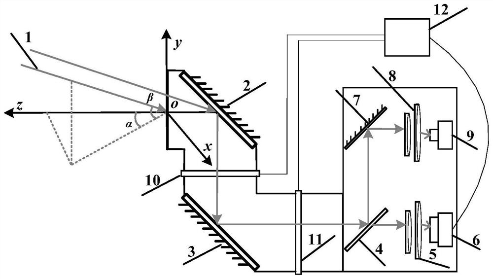
[0020] like figure 1 As shown in the figure, a periscope laser communication terminal decoupling tracking system of the present invention includes an incident laser beam 1, an elevation axis rotating plane mirror 2, an azimuth axis rotating plane mirror 3, a tracking and communication detection beam splitter 4, a tracking focusing lens 5, Imaging camera 6 , mirror 7 , communication focusing lens 8 , communication detector 9 , pitch axis actuator 10 , azimuth axis actuator 11 and servo controller 12 .

[0021] The imaging camera 6 , the pitch axis actuator 10 and the azimuth axis actuator 11 are respectively connected to the servo controller 12 .

[0022] The pitch axis rotation plane mirror 2 and the azimuth axis rotation plane mirror 3 are arranged in parallel, the pitch axis actuator 10 controls the pitch axis rotation plane mirror 2 to rotate in the directi...


PUM


Abstract

A decoupling tracking method for a periscope laser communication terminal belongs to the field of space laser communication, and aims at the tracking coordinates caused by the constant change of the relative position between a rotating plane mirror and an imaging detection sensor in a periscope light and small laser communication terminal. Coupling problem, this method refers to the concept of calibrating the zero point of the coupling coordinate and deriving the decoupling model. In view of the constantly changing relative position between the incident beam and the rotating plane mirror installed on the azimuth and pitch axes of the periscope terminal, combined with the turntable The method of obtaining the off-target amount of the incident light spot after coordinate decoupling with real-time characteristics significantly improves the working efficiency of each actuator of the communication system. The adoption of this method enables the communication servo system to obtain accurate feedback of the target beam position deviation in real time, reduces the complexity of the tracking process caused by structural factors, ensures the accuracy of tracking the incident laser beam misses, and improves the tracking accuracy and stability. .

Description

technical field [0001] The invention relates to a decoupling technology of a laser communication servo system, in particular to a decoupling tracking method of a periscope laser communication terminal, which belongs to the field of space laser communication. Background technique [0002] The space laser communication system uses laser as the information carrier to establish a communication terminal for high-speed data communication link. It is an effective means to establish a long-distance communication network. With the continuous development of application requirements such as satellite launch carrying light and small communication loads, the design of laser communication terminals tends to be more highly integrated, miniaturized and lightweight. The periscope communication system is a commonly used small-diameter design method with a small moment of inertia. It mainly realizes spatial scanning and transmission of receiving and sending beams through two plane mirrors inst...

Claims


Application Information

Patent Timeline
Patent Type & Authority Patents(China)
IPC IPC(8): G01B11/26G01B11/00H04B10/80
CPCG01B11/26G01B11/002H04B10/801
Inventor 张敏韩杰佟首峰张鹏岳丹
Owner CHANGCHUN UNIV OF SCI & TECH
Why Eureka
Try Eureka