
Method and device for synchronizing data of I region and IV region of power monitoring system

A power monitoring and data synchronization technology, applied in the direction of electrical digital data processing, data processing applications, structured data retrieval, etc., can solve problems such as service management, unfavorable modification requirements of code changes, failure to pass through the operating system, etc., to improve real-time performance , solve the real-time requirements and meet the system requirements

Active Publication Date: 2021-08-10
上海许继电气有限公司 +2
View PDF9 Cites 0 Cited by
  • Summary
  • Abstract
  • Description
  • Claims
  • Application Information

AI Technical Summary

Problems solved by technology

The above technology has the following disadvantages: First, it only supports relational databases. In the past, the synchronization requirements were aimed at different relational databases. Therefore, the program only reads certain tables in relational databases. In order to solve the sql of different relational databases, Sentence differences, save the data in the database table as txt custom format, and then the receiver program reassembles the sql statement according to the sql format of the database and writes it into the receiver database; the second is that real-time synchronization cannot be achieved, and the new generation of monitoring system Real-time synchronization of data in areas I and IV is required. The previous solution was to write a timing function in the program to read and write once a day, which could not meet the latest real-time data synchronization requirements.
The third is that it cannot be managed. Since reading and writing are directly controlled by the program, the service management cannot be performed through the operating system. If modification is required, code modification is required, which is not conducive to adapting to the modification needs of different scenarios.

Method used


Image

  • Method and device for synchronizing data of I region and IV region of power monitoring system
  • Method and device for synchronizing data of I region and IV region of power monitoring system
  • Method and device for synchronizing data of I region and IV region of power monitoring system

Examples


Embodiment Construction

[0041] In order to make the object, technical solution and advantages of the present invention clearer, the present invention will be further described in detail below in combination with specific embodiments and with reference to the accompanying drawings. It should be understood that these descriptions are exemplary only, and are not intended to limit the scope of the present invention. Also, in the following description, descriptions of well-known structures and techniques are omitted to avoid unnecessarily obscuring the concept of the present invention.

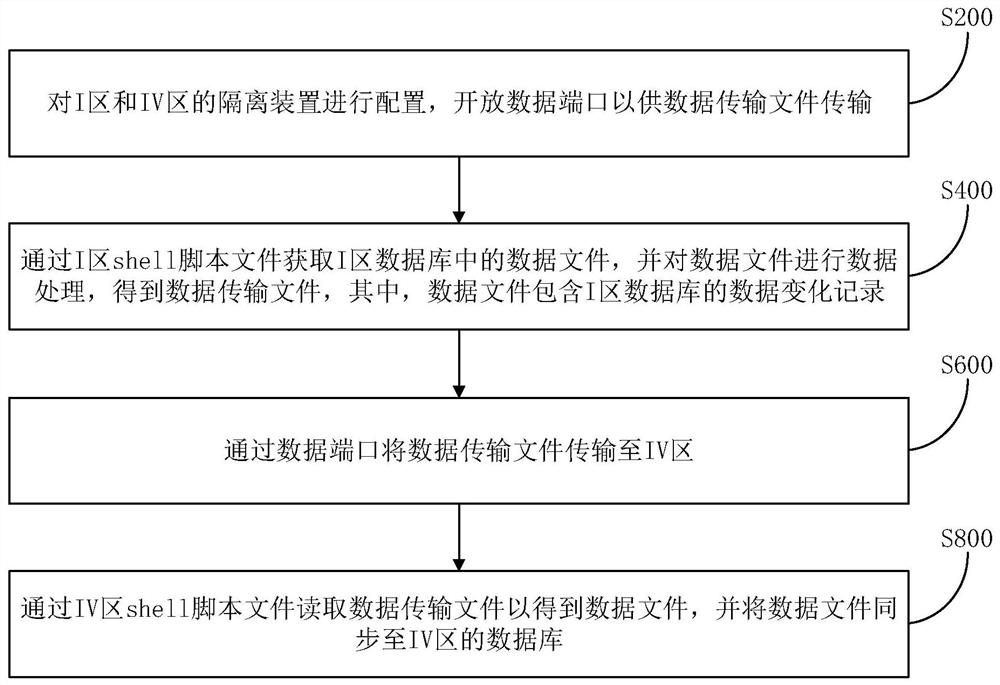
[0042] figure 1 It is a flow chart of the data synchronization method for areas I and IV of the power monitoring system provided by the embodiment of the present invention.

[0043] Please refer to figure 1 , The first aspect of the embodiments of the present invention provides a method for synchronizing data in areas I and IV of the power monitoring system, comprising the following steps:

[0044] S200, configure the ...


PUM


Abstract

The invention discloses a data synchronization method and device for an I area and an IV area of a power monitoring system, and the method comprises the steps: configuring isolation devices of the I area and the IV area, and opening a data port for the transmission of a data transmission file; obtaining a data file in the I-area database through the I-area shell script file, conducting data processing on the data file, and obtaining a data transmission file, wherein the data file comprises a data change record of the I-area database; transmitting the data transmission file to the IV area through the data port; and reading the data transmission file through the IV region shell script file to obtain a data file, and synchronizing the data file to a database of the IV region. The data file containing the data change record in the I-region database is obtained in real time through the I-region shell script file and transmitted to the IV region through the data ports of the I-region and IV-region isolation devices for data synchronization, so that the real-time requirement problem of data synchronization is solved, the real-time performance of system data synchronization is improved, and the system requirement is met.

Description

technical field [0001] The invention relates to the technical field of power system data transmission, in particular to a method and device for synchronizing data in areas I and IV of a power monitoring system. Background technique [0002] At present, the security protection of the monitoring system follows the provisions of GB / T 36572 "Guidelines for Network Security Protection of Electric Power Monitoring System", and is divided into areas I, II, and IV. Zones I and II adopt firewalls horizontally, and Zones I and IV adopt forward and reverse isolation devices for partitioning. After the isolation of I and IV areas, data synchronization has become an urgent problem to be solved. This paper provides a method for data synchronization of I and IV areas through the isolation device. [0003] The previous solution to the data synchronization of the isolation device was to save the data in the database table to be synchronized as a txt file in the transmission folder of the is...

Claims


Application Information

Patent Timeline
Patent Type & Authority Applications(China)
IPC IPC(8): G06F16/178G06F16/27G06Q50/06
CPCG06F16/178G06F16/27G06Q50/06
Inventor 王嘉劼王志轩尹海发杨明伟周昊马梦冬郑天齐王世奇赵德基邬军军高玉宝李建张漪陈鹏黄保莉沈永良
Owner 上海许继电气有限公司
Learn More