Control method of vehicle semi-active suspension system with vibration energy recovery function

A vibration energy recovery, semi-active suspension technology, applied in the direction of suspension, vehicle spring, elastic suspension, etc., can solve the problems of complex structure, low energy utilization rate of automobiles, and high accuracy of mathematical models.

Active Publication Date: 2019-04-19
XIAN UNIV OF SCI & TECH
View PDF8 Cites 0 Cited by
  • Summary
  • Abstract
  • Description
  • Claims
  • Application Information

AI Technical Summary

Problems solved by technology

Although the semi-active suspension shock absorber can realize the semi-active function, its structure is complex, difficult to produce and not easy to maintain, and at the same time, the production cost is high, and it needs to consume the energy of the vehicle itself
[0005] In recent years, due to the lack of resources and environmental problems such as air pollution, people have paid more and more attention to energy issues. Human beings have sought various methods to improve energy efficiency. Automobiles are one of the indispensable means of transportation in modern society. However, The energy utilization rate of the car is very low, the energy of the engine is generally less than 40%, most of the energy is dissipated in the atmosphere in the form of heat energy, and the braking of the car will also dissipate part of the energy. Vibration is an inevitable problem in the process of driving a car. Most traditional car suspensions convert vibration energy into heat energy through shock absorbers and dissipate it into the atmosphere, thus consuming a lot of energy in the car. Recycling has always been a hot and difficult issue in academic circles at home and abroad.
[0006] At present, the control algorithms of most controllable suspension control systems mostly use relatively simple algorithms. Each algorithm has its own advantages and also has its own shortcomings. frame deflection, but the improvement effect on vehicle body acceleration is unsatisfactory. Ground canopy control can improve vehicle body acceleration very well, but it has little improvement on suspension dynamic deflection. Although fuzzy control can comprehensively consider vehicle body acceleration, suspension dynamic deflection and tire dynamic However, it has high requirements on the accuracy of the mathematical model of the suspension system. At the same time, fuzzy control requires continuous accumulation and improvement of fuzzy control rules. Therefore, a single use of a certain algorithm will make the control system not perfect. At the same time, the automobile suspension system is an important A system with high real-time requirements, but most single control rules cannot meet the requirements of reducing or eliminating the time lag of the control system, but for the vehicle controllable suspension system, it includes many time lag links, such as: the time of the sensor collecting signal process Delay; the time delay when the signal is transmitted from the sensor to the controller; the time delay calculated by the controller; the time delay when the control signal is transmitted from the controller to the hydraulic cylinder; the time delay of the hydraulic cylinder action; the time delay generated by the hydraulic cylinder to establish control, etc.
The time lag will not only affect the performance of the suspension system, but also may lead to serious "wheel jump" phenomenon and cause the suspension system to become unstable, thus seriously threatening the safety of the car

Method used


Image

  • Control method of vehicle semi-active suspension system with vibration energy recovery function
  • Control method of vehicle semi-active suspension system with vibration energy recovery function
  • Control method of vehicle semi-active suspension system with vibration energy recovery function

Examples


Embodiment Construction

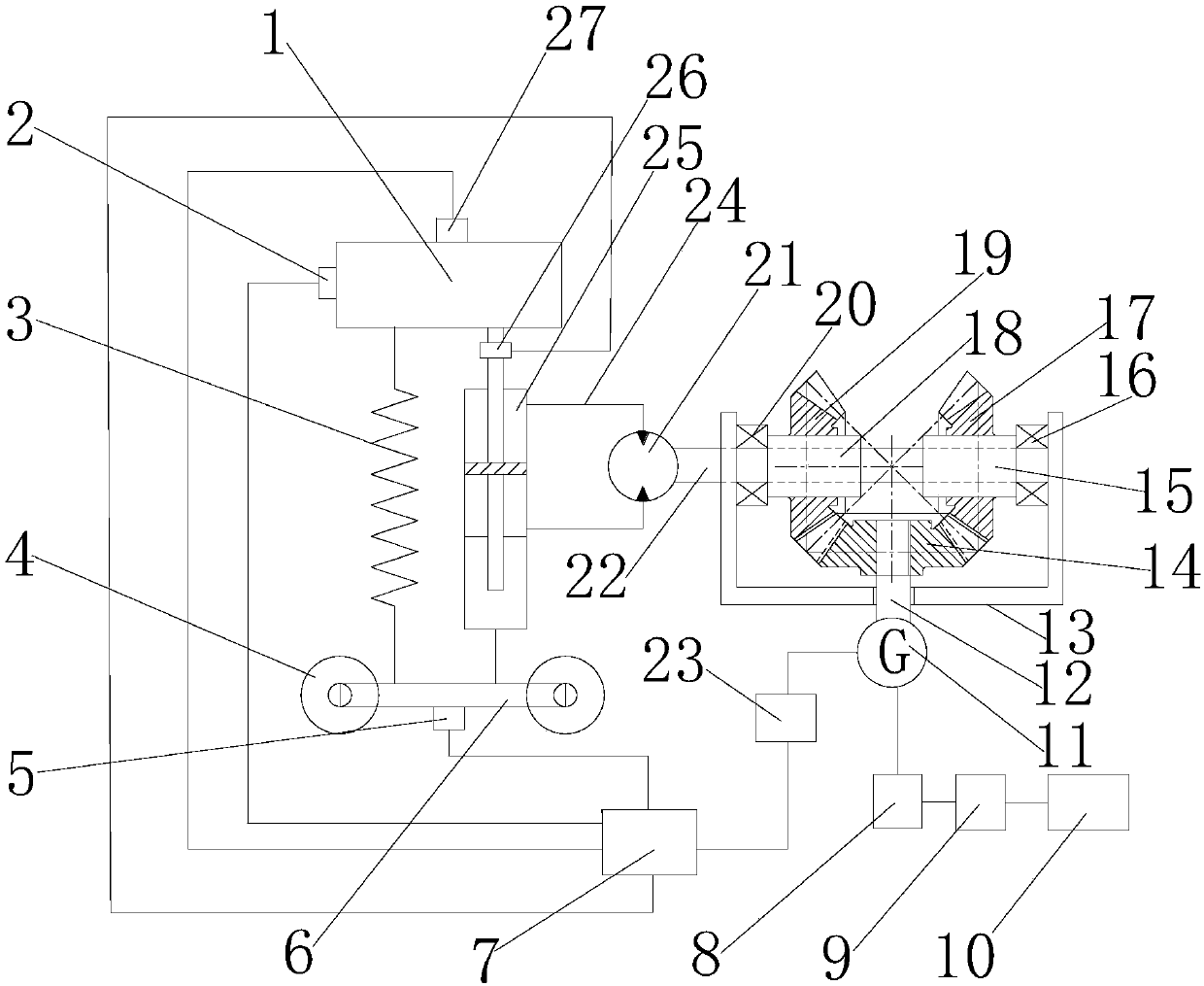
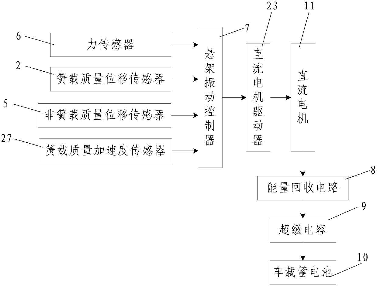
[0085] Such as figure 1 and figure 2 As shown, the vehicle semi-active suspension system with vibration energy recovery function of the present invention includes a damper and a spring 3 arranged side by side between the vehicle frame 1 and the vehicle axle 6, as well as a control system and an energy recovery system;

[0086] The damper includes a hydraulic cylinder 25, a hydraulic motor 21 and a DC motor 11. The hydraulic cylinder 25 and the spring 3 are arranged between the vehicle frame 1 and the axle 6 in parallel. The two ends of the spring 3 are connected to the vehicle frame 1 respectively. It is connected with the vehicle axle 6, the base of the hydraulic cylinder 25 is connected with the vehicle axle 6, the piston rod of the hydraulic cylinder 25 is connected with the vehicle frame 1, and the hydraulic cylinder 25 is connected with the hydraulic motor 21 through the hydraulic pipeline 24. The output shaft of the hydraulic motor 21 is connected with a first transmis...


PUM


Abstract

The invention discloses a control method of a vehicle semi-active suspension system with a vibration energy recovery function. The vehicle semi-active suspension system includes a damper, a spring, a control system and an energy recovery system; the damper includes a hydraulic cylinder, a hydraulic motor, DC motor, first transmission shaft, first roller clutch, second roller clutch, first bevel gear, second bevel gear, third bevel gear and second transmission shaft; the control system includes suspension vibration controller, force A sensor, a sprung mass acceleration sensor, a sprung mass displacement sensor, an unsprung mass displacement sensor and a DC motor driver; the energy recovery system includes an energy recovery circuit and a supercapacitor; and the control method includes two steps. The invention has high working stability and reliability, high energy feeding efficiency, can effectively prolong the service life of the vehicle-mounted storage battery, and can timely adjust the parameters of the semi-active suspension so that the semi-active suspension is in the best vibration reduction state.

Description

technical field [0001] The invention belongs to the technical field of automobile suspension systems, and in particular relates to a control method of a vehicle semi-active suspension system with a vibration energy recovery function. Background technique [0002] During the driving process of the car, due to the unevenness of the road surface and the vibration of the engine itself, the relative displacement between the sprung mass and the unsprung mass of the car is caused, which causes the car to vibrate. Most traditional suspensions use springs with constant stiffness and dampers with constant damping coefficients to form the core components of the automobile suspension system. However, due to the stiffness of the springs and the damping coefficient of the damper, they cannot be changed in real time according to the uneven characteristics of the road surface. , Therefore, the traditional suspension has poor adaptability to the road surface, and the vibration reduction effe...

Claims


Application Information

Patent Timeline
Patent Type & Authority Patents(China)
IPC IPC(8): B60G13/18B60G17/018
CPCB60G13/18B60G17/0182B60G2202/25
Inventor 寇发荣范养强
Owner XIAN UNIV OF SCI & TECH
Why Eureka
Try Eureka