Method for measuring size of optical target in real time under endoscope

A technology for target size and real-time measurement, applied in image analysis, image enhancement, instruments, etc., can solve the problems of low endoscopy efficiency and inability to measure without reference objects, so as to reduce workload, better judge the situation, and improve efficiency. and success rate

Active Publication Date: 2021-08-10
NANKAI UNIV
View PDF10 Cites 3 Cited by
  • Summary
  • Abstract
  • Description
  • Claims
  • Application Information

AI Technical Summary

Problems solved by technology

[0005] The purpose of the present invention is to solve the problem that there is no reference object that cannot be measured in the existing size measurement method that uses the instrument in the endoscopic image as a reference, and the endoscopic examination efficiency that exists in the si

Method used


Image

  • Method for measuring size of optical target in real time under endoscope
  • Method for measuring size of optical target in real time under endoscope
  • Method for measuring size of optical target in real time under endoscope

Examples


Embodiment 1

[0038] The specific implementation manners of the present invention will be further described in detail below in conjunction with the drawings and specific implementation manners. The following examples are used to illustrate the present invention, but are not intended to limit the scope of the present invention.

[0039] Example 1:

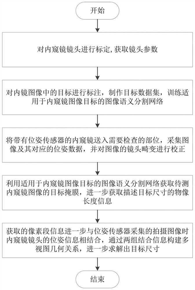
[0040] The invention discloses a method for real-time measurement of the size of an optical target under an endoscope. The method flow is as follows figure 1 As shown, the following systems can be used:

[0041] The system is mainly composed of three parts: electronic endoscope, electromagnetic tracker and computer. The endoscope is operated by professionals, and is responsible for collecting image information in the field of view and transmitting it to the computer. The electromagnetic tracker is responsible for collecting the pose information of the electromagnetic sensor attached to the endoscope and sending it to the computer. The compute...


PUM


Abstract

The invention provides a method for measuring the size of an optical target under an endoscope in real time. The method comprises the following steps: calibrating a lens of the endoscope; training an image semantic segmentation network suitable for the endoscope image target; carrying out target segmentation on an endoscope image in the endoscope examination, extracting size information of the object image, and recording corresponding pose data; and calculating the size of the to-be-measured target through a multi-view geometrical relationship by using the size information of the two groups of object images and the pose data of the two groups of object images. According to the method, the target in the endoscope image can be tracked in real time on the premise of not changing the current endoscope examination program, the size of the target is accurately measured, and the examination efficiency and accuracy are improved.

Description

technical field [0001] The invention relates to the technical field of electronic endoscope imaging inspection, in particular to a target size measurement method for endoscopic inspection based on a pose sensor and a monocular electronic endoscope. Background technique [0002] In the past few decades, electronic endoscopy has become a key technology in industrial inspection, clinical minimally invasive inspection and minimally invasive surgery. The electronic endoscope conducts the image signal through the CCD or camera instead of the fiber optic bundle, and transmits the image to the monitor located outside the body to display the image. The observer can make a judgment by determining whether the target in the image is normal or abnormal. This requires observers to have their own experience in detecting anomalies and further grading their severity according to their size. [0003] However, due to the limitation of the working space, many endoscopic lenses are only equippe...

Claims


Application Information

Patent Timeline
IPC IPC(8): G06T7/62G06T5/00G06T7/73G06T7/80G06T7/11
CPCG06T7/62G06T5/006G06T7/73G06T7/80G06T7/11G06T2207/10068
Inventor 代煜李睿陈公平赵煜张建勋
Owner NANKAI UNIV
Why Eureka
Try Eureka