Thermal energy conversion and utilization equipment utilizing photovoltaic power generation

A technology of energy conversion and photovoltaic power generation, which is applied in the direction of photovoltaic power generation, photovoltaic thermoelectric hybrid power generation, lighting and heating equipment, etc., can solve the problems of untimely conversion, reduced device utilization efficiency, and reduced conversion efficiency, so as to reduce the use cost and improve The effect of improving conversion efficiency and improving usage efficiency

Pending Publication Date: 2021-08-10
魏巍
View PDF0 Cites 2 Cited by
  • Summary
  • Abstract
  • Description
  • Claims
  • Application Information

AI Technical Summary

Problems solved by technology

[0006] The present invention provides a thermal energy conversion and utilization equipment using photovoltaic power generation, one of the purposes is to have the ability of heat cycle absorption, to solve the problem that when the photovoltaic power generation device is in use, a certain amount of heat will be generated, and the heat will not be transformed during transmission. Timely, but the heat utilization is not complete, which leads to the reduction of the utilization efficiency of the device and the reduction of the conversion efficiency; another purpose is to solve the problem that if the outer surface of the photovoltaic power generation device is not cleaned in time, it will affect the performance of the photovoltaic device. Power generation efficiency, and manual cleaning is a waste of time, resulting in a decrease in the use efficiency of the device and an increase in the use cost, in order to improve the use efficiency of the device and reduce the use cost

Method used


Image

  • Thermal energy conversion and utilization equipment utilizing photovoltaic power generation
  • Thermal energy conversion and utilization equipment utilizing photovoltaic power generation
  • Thermal energy conversion and utilization equipment utilizing photovoltaic power generation

Examples


Embodiment 1

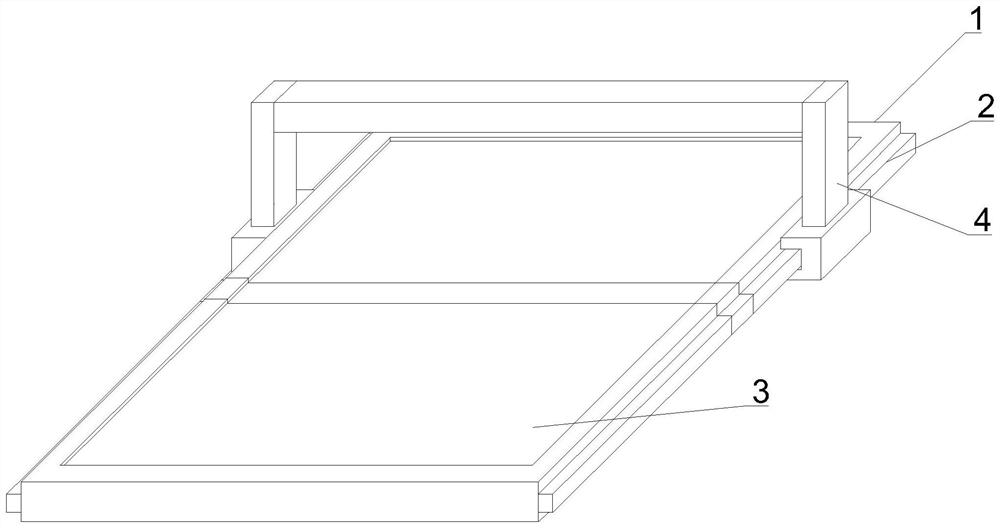
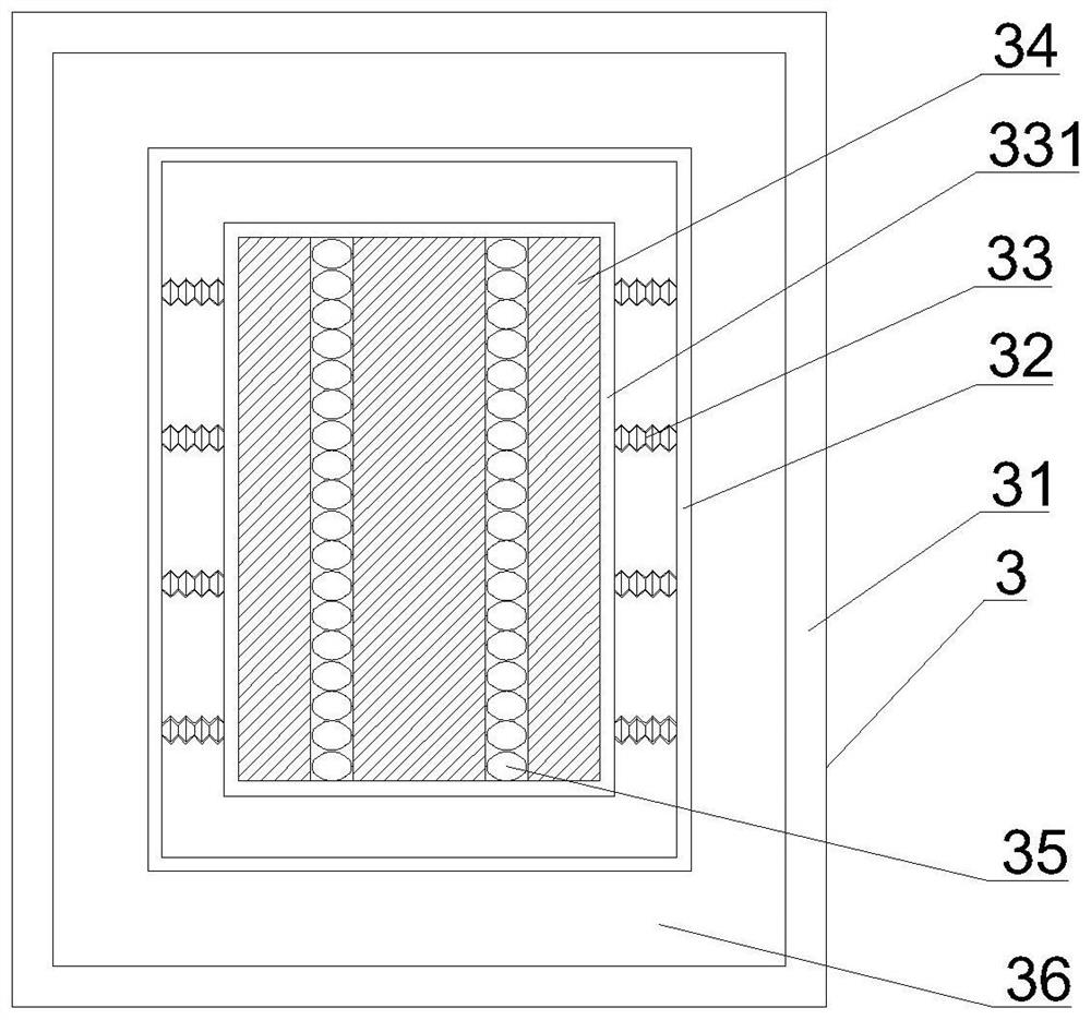
[0048] Such as Figure 1-8 As shown, the present invention provides a thermal energy conversion and utilization device utilizing photovoltaic power generation, including a solar panel device body 1, the solar panel device body 1 includes an outer shell 2, and the inner surface of the outer shell 2 is fixedly connected with solar energy. Panel 3, the outer surface of the solar panel 3 is movably connected with a dust removal device 4, the solar panel 3 includes a ferrule 31, the outer surface of the ferrule 31 is fixedly connected with the inner surface of the outer shell 2, and the interior of the ferrule 31 is fixedly connected There is a circulation pipe 36, and the dust removal device 4 includes a chute 41, the inner surface of the chute 41 is movably connected with the outer surface of the ferrule 31, the outer surface of the chute 41 is provided with a slot 42, and the inner surface of the circulation pipe 36 is Fixedly connected with an inner protective shell 32, the inn...

Embodiment 2

[0052] Such as Figure 1-8 As shown, on the basis of Embodiment 1, the present invention provides a technical solution: preferably, the dust suction pipe 452 includes a U-shaped ferrule 4521, the outer surface of the U-shaped ferrule 4521 and the output shaft of the second rotator 451 The outer surface of the U-shaped ferrule 4521 is movably connected to the inner wall of the U-shaped ferrule 4521, and the inner wall of the U-shaped ferrule 4521 is movably connected to the fan 4524. One end of the suction head 4523 is fixedly connected to the sleeve 4522. A sprinkler 4525 is fixedly connected to the inside of the pipe 4522 .

[0053] In this embodiment, the cooperation between the casing 4522, the suction head 4523, the fan 4524 and the sprinkler 4525 is adopted, and the suction force generated when the fan 4524 rotates and the suction head 4523 cooperate to suck the dust, and then use the sleeve The pipe 4522 transports the dust to the sprinkler 4525, and the dust is wetted ...

Embodiment 3

[0055] Such as Figure 1-8 As shown, on the basis of Embodiment 1, the present invention provides a technical solution: preferably, the brush 454 includes a second shell 4541, the outer surface of the second shell 4541 is fixedly connected with the outer surface of the rotating ferrule 453, and the second shell 4541 is fixedly connected to the outer surface of the rotating ferrule 453. A heater 4542 is fixedly connected to the inside of the shell 4541, a bristle 4543 is fixedly connected to the outer surface of the shell 2 4541, and a heat conduction wire 4544 is fixedly connected to the inside of the bristle 4543.

[0056] In this embodiment, the cooperation between the second shell 4541, the heater 4542, the bristles 4543 and the heat conduction wire 4544 is adopted, and the heat is transferred to the heat conduction wire 4544 through the cooperation of the second shell 4541 and the heater 4542, and the heat conduction wire 4544 is used to transfer the heat to the heat conduc...


PUM


Abstract

The invention discloses thermal energy conversion and utilization equipment utilizing photovoltaic power generation, belonging to the technical field of photovoltaic power generation. The thermal energy conversion and utilization equipment comprises a solar panel device body, wherein the solar panel device body comprises an outer protective shell, a solar panel is fixedly connected to the inner surface of the outer protective shell, a dust removal device is movably connected to the outer surface of the solar panel, the solar panel comprises a clamping sleeve, and the outer surface of the clamping sleeve is fixedly connected with the inner surface of the outer protective shell. According to the invention, heat is absorbed through a heat absorption sheet, and a pressure is increased by using the principle of thermal expansion and cold contraction; hot air is conveyed to a circulating pipe for cyclic utilization by using cooperation between an air pipe and a heat conduction cylinder, so the problems that the utilization efficiency of a photovoltaic power generation device is reduced and conversion efficiency is reduced as energy utilization is not thorough when a certain amount of heat is generated during usage of a photovoltaic power generation device and is not converted in time during transmission, and the effect of improving the utilization efficiency and the conversion efficiency of the device is achieved.

Description

technical field [0001] The invention relates to thermal energy conversion and utilization equipment, relates to the technical field of photovoltaic power generation, and in particular to thermal energy conversion and utilization equipment utilizing photovoltaic power generation. Background technique [0002] Photovoltaic power generation is a technology that directly converts light energy into electrical energy by using the photovoltaic effect of the semiconductor interface. It is mainly composed of solar panels (components), controllers and inverters. The main components are composed of electronic components. , The solar cells are packaged and protected after being connected in series to form a large-area solar cell module, and then cooperate with power controllers and other components to form a photovoltaic power generation device. [0003] There are following problems at prior art: [0004] 1. When the photovoltaic power generation device is in use, it will generate a ce...

Claims


Application Information

Patent Timeline
Patent Type & Authority Applications(China)
IPC IPC(8): H02S40/10H02S40/44F26B23/00
CPCF26B23/00H02S40/10H02S40/44Y02E10/50Y02E10/60
Inventor 魏巍
Owner 魏巍
Why Eureka
Try Eureka