Femoral artery pneumatic compression device

A femoral artery, sliding connection technology, applied in the field of medical devices, can solve the problems of compression failure, falling, and insufficient fixation, and achieve the effect of improving the fitting effect, enhancing comfort, and improving convenience.

Inactive Publication Date: 2021-08-13
深圳麦普奇医疗科技有限公司
View PDF5 Cites 0 Cited by
  • Summary
  • Abstract
  • Description
  • Claims
  • Application Information

AI Technical Summary

Problems solved by technology

[0003] The purpose of the present invention is to provide a femoral artery pneumatic compression device, which has the advantages of automatic control of the compression force and firm installation to enhance the comfort of the patient, and solves serious complications such as hematoma, limb ischemia, and thrombus if the compression is improper, and cannot be adjusted in real time. Compression pressure, if the compression is too tight, it will affect the blood supply and is not conducive to wound healing; if the compression is too loose, it will not achieve the effect of compression and hemostasis, which is not conducive to the wound repair of the femoral artery puncture site, and at the same time cannot guarantee the comfort of the patient. The position is located on the inner side of the thigh root, which is a special position. When the traditional compressor is pressed, the patient cannot move. Once the knee is slightly bent and moved, it is easy to cause the compressor to shift, deviate or fall, resulting in failure of compression and insufficient fixation. question

Method used


Image

  • Femoral artery pneumatic compression device
  • Femoral artery pneumatic compression device
  • Femoral artery pneumatic compression device

Examples


Embodiment Construction

[0024] The following will clearly and completely describe the technical solutions in the embodiments of the present invention with reference to the accompanying drawings in the embodiments of the present invention. Obviously, the described embodiments are only some, not all, embodiments of the present invention. Based on the embodiments of the present invention, all other embodiments obtained by persons of ordinary skill in the art without making creative efforts belong to the protection scope of the present invention.

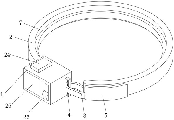
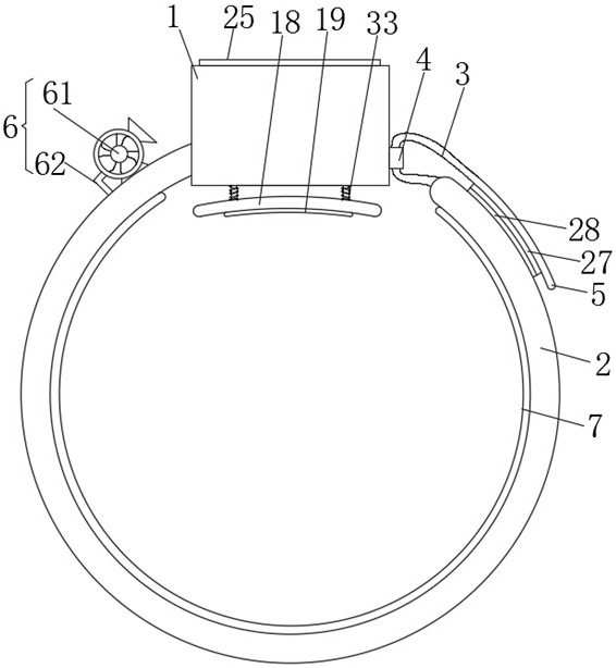
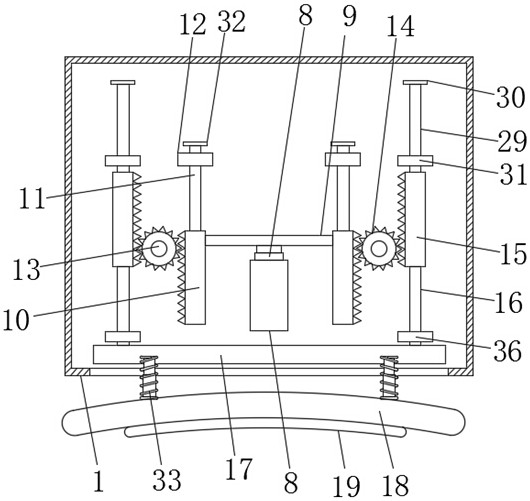
[0025] see Figure 1-6 As shown, the present invention provides a technical solution: a femoral artery pneumatic compression device, including a control box 1, an inflatable restraint belt 2 is installed on the left side of the control box 1, and an adjustment rope 3 is installed on the other end of the inflatable restraint belt 2, and the control box The right side of 1 is bolted with a buckle 4, one end of the adjustment rope 3 runs through the adjustment ro...


PUM


Abstract

The invention relates to the technical field of medical instruments, and discloses a femoral artery pneumatic compression device which comprises a control box, and an inflatable binding belt is installed on the left side of the control box; the thigh femoral artery is sleeved with the inflatable binding belt, the hook face of a hook-and-loop fastener is attached to the hook face of the hook-and-loop fastener through pulling of an adjusting rope, a miniature air blower is started, air flow is driven to enter an inflatable layer through an air inlet pipe, the inflatable layer bulges to be attached to and tightly press the thigh of a patient, therefore the inflatable binding belt is firmly installed, the comfort level of the patient is enhanced, and the attaching effect is improved; an air cylinder drives a push rod to push a first toothed bar to move, the first toothed bar drives a gear to rotate on the surface of a connecting rod and drives a second toothed bar to move, the second toothed bar drives a telescopic rod to push a telescopic plate to move, the telescopic plate drives an arc-shaped pressing plate to extrude an affected part, and a buffer spring is compressed; and an absorbent cotton block absorbs the blood of the patient, and a pressure sensor automatically adjusts the expansion and contraction according to the arterial pressure of an affected part, so that the compression force is automatically controlled, and the convenience is improved.

Description

technical field [0001] The invention relates to the technical field of medical devices, in particular to a femoral artery pneumatic compression device. Background technique [0002] With the continuous development of science and technology, more and more treatment methods appear in tumor treatment. Among them, vascular interventional surgery, as a surgical treatment for malignant trophoblastic tumors, has been widely used in tumor treatment because of its small trauma, easy operation, and accurate intervention site. Vascular interventional surgery usually requires percutaneous femoral artery puncture into the artery, and the common method of femoral artery puncture site wound is to use manual compression. Femoral artery puncture is a common clinical surgical operation. Arterial blood samples are collected, special examinations, Femoral artery puncture is required for pressurized blood transfusion or cardiovascular and cerebrovascular interventional surgery, but the hemostas...

Claims


Application Information

Patent Timeline
Patent Type & Authority Applications(China)
IPC IPC(8): A61B17/135A61F13/06
CPCA61B17/1325A61B17/135A61B17/1355A61F13/06A61F13/00029A61F13/00063A61B2017/12004
Inventor 孙丽娜毛玉兰蔡珂
Owner 深圳麦普奇医疗科技有限公司
Why Eureka
Try Eureka