
Distal radius palmar bone fracture plate

A technology of distal radius and bone plate, applied in the field of medical devices, can solve the problems of easy tilting, insufficient bone grafting, insufficient recovery of radial bone height, etc., and achieve the effect of easy bone grafting and easy exposure

Inactive Publication Date: 2021-08-13
SHANGHAI EAST HOSPITAL EAST HOSPITAL TONGJI UNIV SCHOOL OF MEDICINE
View PDF0 Cites 1 Cited by
  • Summary
  • Abstract
  • Description
  • Claims
  • Application Information

AI Technical Summary

Problems solved by technology

[0004] At present, bone plate treatment mainly faces the following problems: 1. The height of the radius is not restored enough, and it is more likely to be lost due to insufficient bone grafting or osteoporosis; 2. Because the proximal end of the radius is thinner than the distal end of the radius, the distal end of the radius should be fixed first and then the bone plate should be fixed. The proximal end tends to tilt up and deviate from the radius, and the proximal end cannot be fixed with screws; 3. Existing AO and biogenic bone plates are designed according to the anatomical characteristics of the distal end of the radius, and are used for anatomical locking and compression plate, but rarely for anatomical locking Compression plate as reduction template in treatment of distal radius fractures

Method used


Image

  • Distal radius palmar bone fracture plate
  • Distal radius palmar bone fracture plate
  • Distal radius palmar bone fracture plate

Examples


Embodiment 1

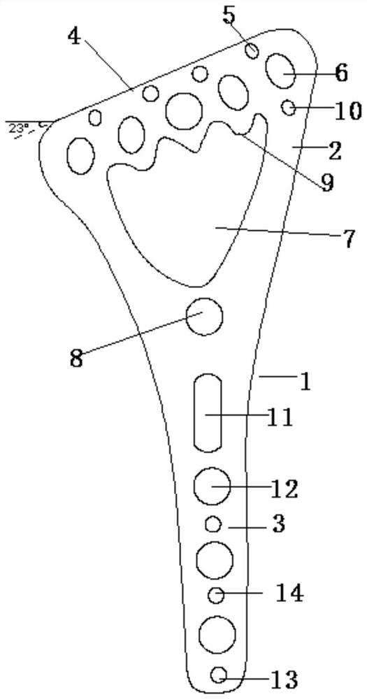
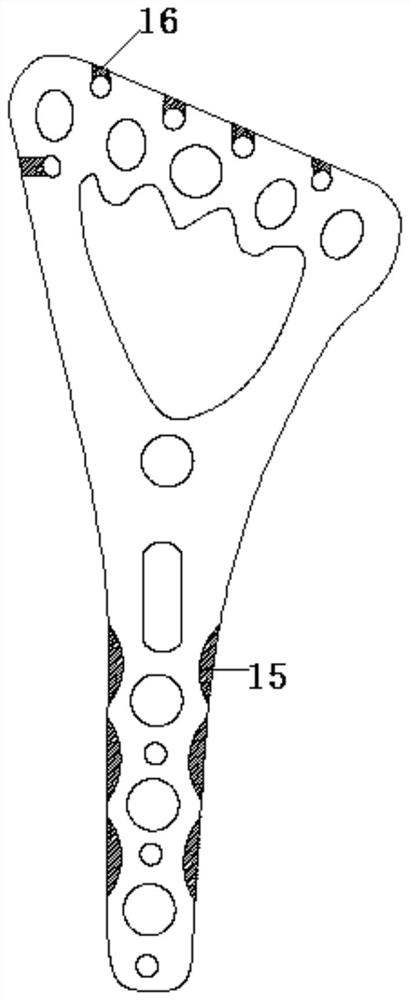
[0022] Such as Figure 1-Figure 3 A volar bone plate at the distal end of the radius is shown, comprising a bone plate body 1, the thickness of the bone plate body 1 is about 1.7-2.5mm, the length is 4.5-10cm, and the width is 0.7-2.1cm. It is the distal end close to the wrist joint segment 2 and the proximal end segment 3, the distal end close to the wrist joint segment 2 is a curved surface structure extending to both sides of the curve, the proximal end segment 3 is a straight structure, and the proximal end segment 3 It is connected with the distal end close to the wrist joint segment 2 in a smooth transition, and is an integral structure. The top surface of the distal end close to the wrist joint segment 2 is a slope structure 4, and the distal end close to the wrist joint segment 2 is sequentially opened with distal ends. The upper Kirschner wire hole 5, the distal upper locking hole 6, the concave hole 7 and the distal lower locking hole 8, the concave hole 7 is shield-...

Embodiment 2

[0024] Such as Figure 1-Figure 3 A volar bone plate at the distal end of the radius is shown, which includes a bone plate body 1, the edge of which is a smooth curved surface structure, with a thickness of about 1.7-2.5 mm, a length of 4.5-10 cm, and a width of 0.7-2.1 cm. The bone plate body 1 is divided into a distal segment close to the wrist joint 2 and a proximal segment 3. The distal segment close to the wrist joint 2 is a curved surface structure extending to both sides in a curve that fits with the shape of the palm side of the distal end of the radius. The proximal section 3 is a straight structure, and the proximal section 3 and the distal end are connected with a smooth transition near the wrist joint section 2, forming an integrated structure. The top surface of the distal end near the wrist joint section 2 is a slope structure 4, and the slope structure 4. The included angle with the horizontal direction is 23°, which is similar to the radius and ulnar deviation ...


PUM


Abstract

The invention discloses a distal radius palmar bone fracture plate. The distal radius palmar bone fracture plate comprises a bone fracture plate body, wherein the bone fracture plate body comprises a distal end section close to a wrist joint and a proximal end section, wherein and the top surface of the distal end section close to the wrist joint is of an inclined surface structure; a distal end upper kirschner wire hole, a distal end upper locking hole, a concave hole and a distal end lower locking hole are sequentially formed in the position, close to the wrist joint, of the distal end from top to bottom; the whole concave hole is in a shield shape; a sawtooth structure is arranged on the upper edge of the concave hole; a distal end lower kirschner wire hole is formed under the distal end upper locking hole; the distal end lower locking hole is positioned in the middle, close to the lower end of the wrist joint section, of the distal end; the proximal end section is sequentially provided with a sliding hole, proximal end locking holes and near-end lower kirschner wire holes from top to bottom; and proximal end upper kirschner wire holes are formed between the adjacent proximal end locking holes. The anatomical design of the bone fracture plate conforms to the anatomical characteristics of the distal radius, the bone fracture plate can be used as a reduction template for comminuted fracture, and excessive soft tissue stripping and blood supply stimulation damage are avoided.

Description

technical field [0001] The invention relates to the technical field of medical devices, in particular to a volar bone plate at the distal end of the radius. Background technique [0002] The treatment of distal radius fractures mainly adopts external fixator and bone plate fixation. External fixators are mainly used for the treatment of obviously comminuted, open fractures, or distal radius fractures with severe soft tissue defects, but there are risks of needle tract infection, loss of reduction, and sensory damage to the radial nerve. Complex regional pain syndrome type I may also be present, especially if the external fixator is used for long-term, vigorous traction. Although open reduction and bone plate internal fixation can avoid the above problems to a certain extent, improper selection of bone plate and poor fracture reduction during operation will still lead to high complications, such as malunion (shortening of radius height), osteoarticular Inflammation, wrist d...

Claims


Application Information

Patent Timeline
Patent Type & Authority Applications(China)
IPC IPC(8): A61B17/80
CPCA61B17/8061A61B17/808
Inventor 刘立峰方楠彭青武乐高硕
Owner SHANGHAI EAST HOSPITAL EAST HOSPITAL TONGJI UNIV SCHOOL OF MEDICINE
Learn More