Aeration pipe and self-cleaning method

An aeration tube and self-cleaning technology, applied in chemical instruments and methods, special treatment targets, sustainable biological treatment, etc., can solve problems such as membrane fouling, uneven bubbles, and sludge drying by heat

Pending Publication Date: 2021-08-13
济南槐荫尘峰环保技术开发中心
View PDF0 Cites 1 Cited by
  • Summary
  • Abstract
  • Description
  • Claims
  • Application Information

AI Technical Summary

Problems solved by technology

The aeration system usually needs to run continuously and must not stop working. Once the fan is stopped for some reason, the hot air will be held in the inner tube of the aeration. Over time, the sludge at the aeration orifice will be heated and dried and the hole will be blocked. mouth, and thus lead to poor aeration or uneven bubbles, etc.
In the MBR system, the membrane scrubbing aeration generally adopts the perforate...

Method used


Image

  • Aeration pipe and self-cleaning method
  • Aeration pipe and self-cleaning method
  • Aeration pipe and self-cleaning method

Examples


Embodiment 1

[0129] Embodiment 1: in combination with all accompanying drawings; Option 1:

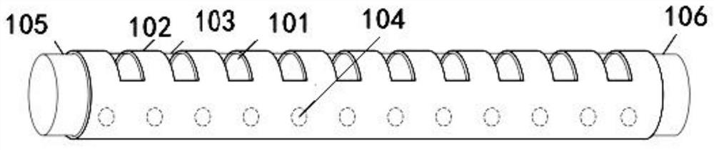
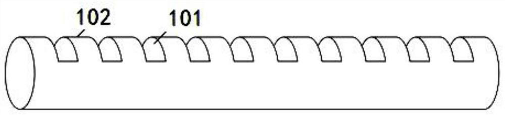
[0130] An aeration tube, characterized in that it includes an outer membrane 102 and an aeration inner tube 103; the outer membrane 102 is made of elastic material, and several diversion ports 101 are arranged on it;

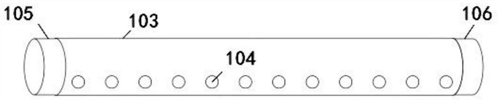
[0131] One end of the aeration inner tube 103 is sealed, and the other end of the aeration inner tube 103 is connected with the air supply pipeline of the aeration system; the aeration inner tube 103 is provided with some aeration inner tube side holes 104;

[0132] The outer membrane 102 is set on the outside of the aeration inner tube 103 .

[0133]The substantive technical effect and the realization process of the technical solution here are as follows: using the aeration tube as described in any one of the above claims, one is that the aeration inner tube is uniformly provided with a larger aeration inner tube The side holes 104 form larger air bubbles, reduce resistance and sav...

Embodiment 2

[0135] Embodiment 2: As a further improved solution or a side-by-side solution or an optional independent solution, the side hole 104 of the aeration inner tube is opened along the axial direction of the aeration inner tube 103, and the side hole 104 axis of the aeration inner tube Perpendicular to the tube wall of the aeration inner tube 103 , the opening area is located at 1 / 3-1 / 2 below the horizontal plane of the axis. The substantive technical effect and the realization process of the technical solution here are as follows: This embodiment provides specific dimensions, and similar dimensions are all within the scope of protection of this patent.

Embodiment 3

[0136] Embodiment 3: As a further improved solution or a side-by-side solution or an optional independent solution, the lower edge of the diversion port 101 is parallel to the axis of the adventitia 102, and the height of the diversion port 101 is 1 / of the diameter of the adventitia 102 3. The substantive technical effect and the realization process of the technical solution here are as follows: This embodiment provides specific dimensions, and similar dimensions are all within the scope of protection of this patent.


PUM


Abstract

The invention relates to the field of sewage treatment, and especially relates to an aeration pipe and a self-cleaning method. The aeration pipe comprises an outer membrane (102) and an aeration inner pipe (103); the outer membrane (102) is made of an elastic material, and a plurality of flow guide ports (101) are formed in the outer membrane (102); one end of the aeration inner pipe (103) is sealed, and the other end of the aeration inner pipe (103) is connected with an air supply pipeline of an aeration system; a plurality of aeration inner pipe side holes (104) are formed in the aeration inner pipe (103); and the outer membrane (102) sleeves the outer side of the aeration inner pipe (103). When large bubbles flow out of the side holes (104) of the aeration inner pipe and then are discharged through a flow guide port on the outer membrane (102), the pressure at the flow guide port is reduced, the outer membrane retracts by virtue of elasticity, and the gas is blocked again, reduced or interrupted; meanwhile, under the conveying action of a fan, the outer membrane of the flow guide port is opened again by the pressure of the air, a large amount of bubbles flow out, and continuous oscillation turbulence is formed.

Description

technical field [0001] The invention relates to the field of sewage treatment, in particular to an aeration pipe and a self-cleaning method. Background technique [0002] From a technical point of view, at present, the bottom aeration inner pipeline is mainly used in the MBR membrane project, and the aeration is realized by using the aeration holes arranged on the aeration inner pipeline. The aeration system usually needs to run continuously and must not stop working. Once the fan is stopped for some reason, the hot air will be held in the inner tube of the aeration. Over time, the sludge at the aeration orifice will be heated and dried and the hole will be blocked. mouth, and then lead to poor aeration or uneven bubbles and other phenomena. In the MBR system, the membrane scrubbing aeration generally adopts the perforated aeration method with large bubbles. When the system is resting or performing chemical cleaning, the aeration is usually stopped, so it is easier to block...

Claims


Application Information

Patent Timeline
IPC IPC(8): C02F3/12
CPCC02F3/1268C02F2303/14Y02W10/10
Inventor 陈峰陈丹周少奇
Owner 济南槐荫尘峰环保技术开发中心
Why Eureka
Try Eureka