Supercharge Your Innovation With Domain-Expert AI Agents!

Building photovoltaic integrated wind-resistant roof system

A roofing system and photovoltaic technology, which is applied to buildings, roofs, photovoltaic modules, etc., can solve the problems that roof panels are difficult to meet the needs of different regions, and the user consumes a lot of manpower, material resources and financial resources, etc., to achieve the enhancement of the overall wind resistance ability , Enhanced wind resistance and improved bearing capacity

Inactive Publication Date: 2021-08-13
CENT INT GROUP
View PDF7 Cites 1 Cited by
  • Summary
  • Abstract
  • Description
  • Claims
  • Application Information

AI Technical Summary

Problems solved by technology

The user of the building at the initial design stage may only propose one or two types of use requirements, but the user may raise new requirements during the use process, such as wanting to turn the roof into a planted roof, or want to increase solar energy on the roof Photovoltaics, etc., often the metal roof panel type selected in the early design stage can only meet the original needs. To meet the new needs of the user, the only way is to remove the original roof and lay a new roof according to the demand, which requires the user to spend a lot of money. human, material and financial resources
At the same time, it is difficult for one type of panel to adapt to different regions. For example, the snow load in the northeast region is often relatively large, which requires the roof panel to have a good load bearing capacity. Typhoons in coastal areas are more frequent, and the roof panel is required to have good Wind resistance. The large temperature difference between day and night in Northwest China requires roof panels to have a good ability to resist temperature deformation. At present, the roof panels used are difficult to meet the needs of different regions.

Method used


Image

  • Building photovoltaic integrated wind-resistant roof system
  • Building photovoltaic integrated wind-resistant roof system
  • Building photovoltaic integrated wind-resistant roof system

Examples


Embodiment Construction

[0038] The technical solutions of the present invention will be clearly and completely described below in conjunction with the accompanying drawings. Apparently, the described embodiments are some of the embodiments of the present invention, but not all of them. Based on the embodiments of the present invention, all other embodiments obtained by persons of ordinary skill in the art without making creative efforts belong to the protection scope of the present invention.

[0039] In the description of the present invention, it should be noted that the terms "center", "upper", "lower", "left", "right", "vertical", "horizontal", "inner", "outer" etc. The indicated orientation or positional relationship is based on the orientation or positional relationship shown in the drawings, and is only for the convenience of describing the present invention and simplifying the description, rather than indicating or implying that the referred device or element must have a specific orientation, ...


PUM


Abstract

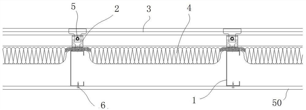
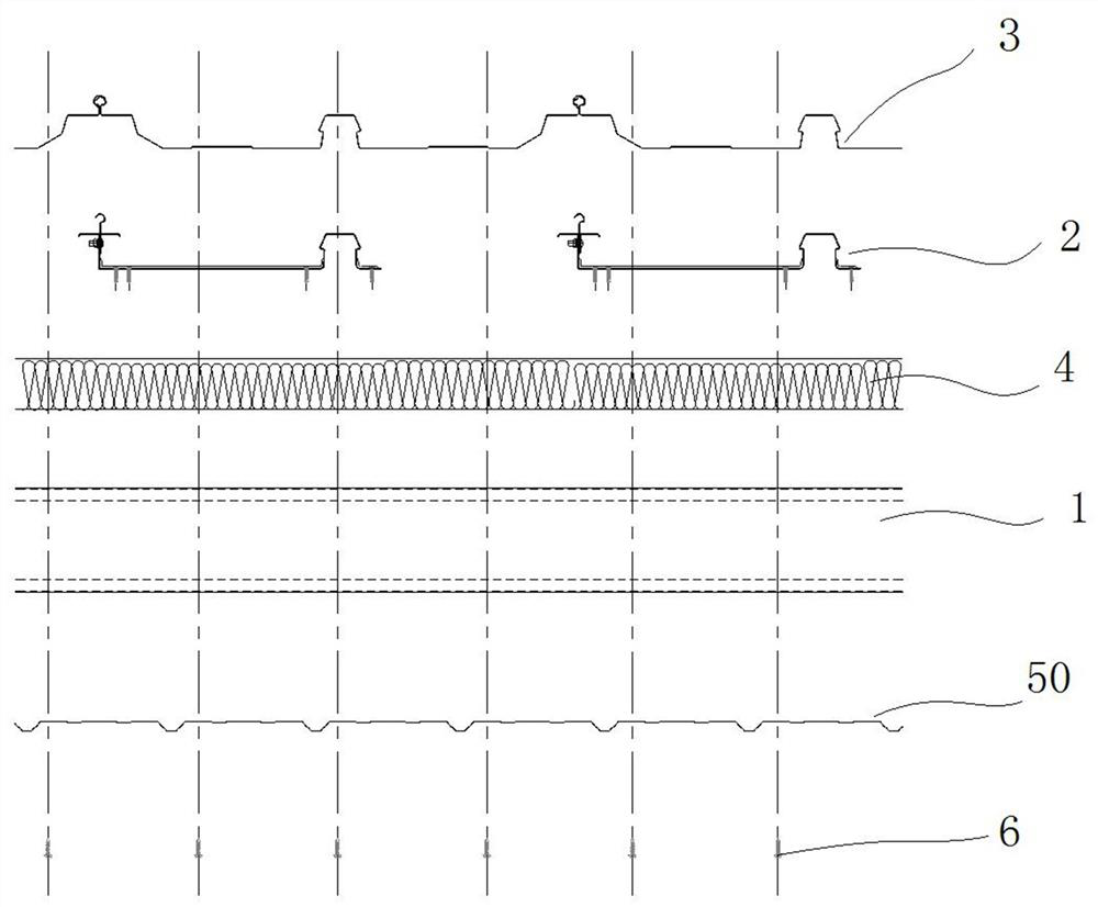
The invention discloses a building photovoltaic integrated wind-resistant roof system. A plurality of fixing seats are fixed on each purline at intervals, roof panels are connected with the fixing seats, heat preservation cotton is laid below the roof panels, each fixing seat comprises a base, a roof panel connecting piece and a supporting table, and the roof panel connecting pieces, the bases and the supporting tables form a whole; and a bottom plate extending in the length direction of the purlines is arranged on one side of each base, a roof panel supporting rib protruding upwards is arranged at the end, away from the corresponding base, of each bottom plate, the roof panel supporting ribs are located between the bases of every two adjacent fixing seats, two side ribs of each roof panel are connected with the roof panel connecting pieces of every two adjacent fixing seats in a buckled mode, panel supporting ribs are further formed on the roof panels, and the bases and the bottom plates close to the roof panel supporting ribs are fixed on the purlines through fastening connecting pieces respectively. According to the system, the bearing capacity of the roof panels is improved, the system can be used for laying photovoltaic panels, walkway plates and the like on a roof, the temperature deformation of the roof panels is eliminated, the single panels are wider, and the construction efficiency is higher.

Description

technical field [0001] The invention relates to the technical field of metal roofs, in particular to a building photovoltaic integrated wind-resistant roof system. Background technique [0002] With the development of society and the advancement of science and technology, people's functional requirements for building roofs have become more and more diverse, especially in the field of metal roofs. From the initial requirements for roofs to have waterproof and thermal insulation functions, now metal roofs are required to meet basic functions. On the basis of this, there are also requirements for various functions such as aesthetic functions, energy-saving functions, and noise reduction functions. The user of the building at the initial design stage may only propose one or two types of use requirements, but the user may raise new requirements during the use process, such as wanting to turn the roof into a planted roof, or want to increase solar energy on the roof Photovoltaics...

Claims


Application Information

Patent Timeline
Patent Type & Authority Applications(China)
IPC IPC(8): E04D3/30E04D3/365E04D13/18H02S20/23
CPCE04D3/30E04D3/365H02S20/23Y02B10/10Y02B10/20Y02E10/50
Inventor 陈俊臣刘爱森马海龙苏航星谢莉
Owner CENT INT GROUP
Features
  • R&D
  • Intellectual Property
  • Life Sciences
  • Materials
  • Tech Scout
  • Unparalleled Data Quality
  • Higher Quality Content
  • 60% Fewer Hallucinations
Learn More