Electrical variable measuring device for electrical resistance characteristics of electronic components
A technology of electronic components and measuring devices, which is applied in the direction of measuring devices, measuring device casings, and measuring electrical variables, etc., can solve the problems of reducing measurement efficiency, affecting the accuracy of electronic component measurement, and not being able to clean dust, so as to avoid measurement efficiency, Avoid the effect of more dust adhesion
- Summary
- Abstract
- Description
- Claims
- Application Information
AI Technical Summary
Problems solved by technology
Method used
Image
Examples
Embodiment 1
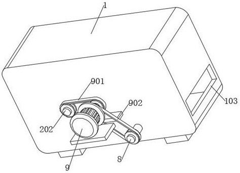
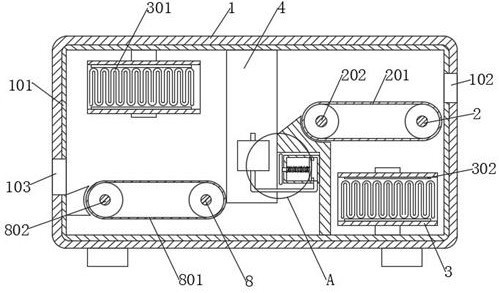
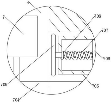
[0029] Embodiment 1: refer to Figure 1-8 , the electrical variable measuring device for the resistance characteristics of electronic components, including a box body 1, an electronic component body 5, and also includes: a material inlet 102 and a material outlet 103, which are respectively provided on both sides of the box body 1; a frame 4 is fixedly connected to the box body The inner wall of the body 1; the self-locking assembly is arranged on the frame 4; the conductive ring 405 is arranged on the self-locking assembly and is plugged and connected with the electronic component body 5; and cooperates with the conductive ring 405 to transmit electrical signals to the electronic component body 5 A signal source, and an oscilloscope cooperating with the conductive ring 405; a cleaning assembly, arranged on one side of the conductive ring 405, for cleaning the dust attached to the electronic component body 5; a reciprocating assembly, arranged on one side of the frame 4, and th...
Embodiment 2
[0035] Embodiment 2: refer to figure 2 , Figure 4 and Figure 7 , the resistance characteristic electrical variable measuring device of the electronic component is basically the same as Embodiment 1, and furthermore, the self-locking assembly includes a motor 9, a reciprocating screw mandrel 402, a support plate 404, and the frame 4 is fixedly connected with a placement plate 401, and the electronic The component body 5 is located on the placement plate 401, the motor 9 is fixedly connected to the side wall of the box body 1, the reciprocating screw rod 402 is rotatably connected to the frame 4, the support plate 404 is screwed to the reciprocating screw rod 402, and the output end of the motor 9 is connected to the reciprocating screw rod 402 is fixedly connected, and the support plate 404 is attached to the electronic component body 5 .
[0036] A guide rod 403 is fixedly connected to the frame 4 , and the guide rod 403 is slidably connected to a support plate 404 .
[...
Embodiment 3
[0038] Embodiment 3: refer to Figure 4 , Figure 5 and Figure 8 , the resistance characteristic electrical variable measuring device of the electronic component is basically the same as Embodiment 1, and furthermore, the cleaning assembly includes a sleeve 6, a support rod 607, and a collar 604, and the sleeve 6 and the collar 604 are all fixedly connected On the supporting plate 404, the supporting rod 607 is fixedly connected to the frame 4, the lower pressing plate 601 is slidably connected in the sleeve one 6, the lower pressing plate 601 is fixedly connected with the inner wall of the sleeve one 6 with a spring one 602, the lower pressing plate 601 and the supporting plate 404 Slidingly connected, the inner wall of the collar 604 is fixedly connected with the nozzle 605 and the brush 606 respectively, and the sleeve one 6 and the nozzle 605 are connected through the conduit one 603 .
[0039] When the self-locking assembly clamps the electronic component body 5, the s...
PUM
 Abstract
Description
Claims
Application Information
 - R&D
- Intellectual Property
- Life Sciences
- Materials
- Tech Scout
- Unparalleled Data Quality
- Higher Quality Content
- 60% Fewer Hallucinations
Browse by: Latest US Patents, China's latest patents, Technical Efficacy Thesaurus, Application Domain, Technology Topic, Popular Technical Reports.
© 2025 PatSnap. All rights reserved.Legal|Privacy policy|Modern Slavery Act Transparency Statement|Sitemap|About US| Contact US: help@patsnap.com


