Controllable temperature and humidity environment box and control circuit

A technology of humidity control and environmental chamber, which is applied in the direction of non-electric variable control, control/regulation system, and simultaneous control of multiple variables, etc., and can solve problems such as single working conditions

Pending Publication Date: 2021-08-13
SHANGHAI JIAO TONG UNIV
View PDF10 Cites 1 Cited by
  • Summary
  • Abstract
  • Description
  • Claims
  • Application Information

AI Technical Summary

Problems solved by technology

[0002] The working range of the current temperature and humidity environmental chamber is usually at a certain high temperature and humidity, and the working conditions are singl

Method used


Image

  • Controllable temperature and humidity environment box and control circuit
  • Controllable temperature and humidity environment box and control circuit
  • Controllable temperature and humidity environment box and control circuit

Examples


Embodiment 1

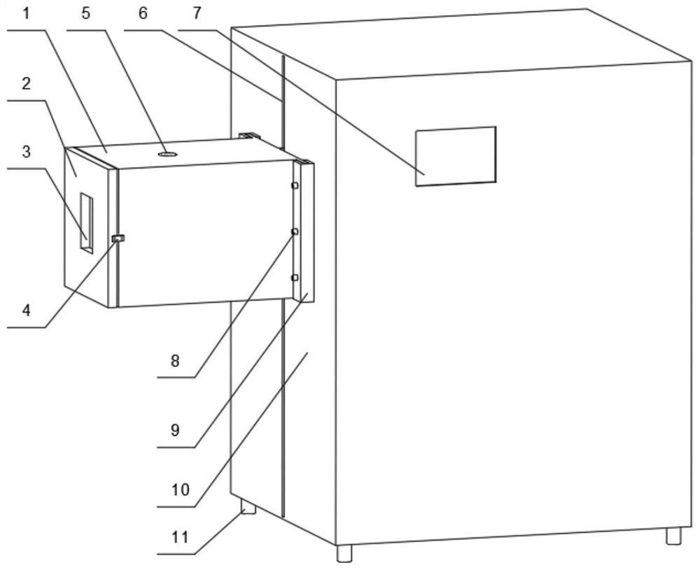
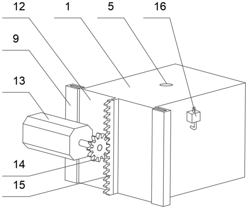
[0067] Such as figure 1 and figure 2 As shown, a controllable temperature and humidity environment box includes: a main environment box 1, a fixed support box 10, a motor 13, a high temperature control unit, a low temperature control unit, a humidity control unit, a control instrument panel 7, and a temperature and humidity meter 24 And fan 22; one side of the main environment box 1 is connected to the side of the fixed support box 10, and the fixed support box 10 is installed with a motor 13 near the inner wall of the main environment box 1 side, and the fixed support box 10 is connected to the motor 13 and passed through the motor 13 Adjust the height; install the high temperature control unit on the inner wall of the main environment box 1 close to the side of the fixed support box 10, install the low temperature control unit on the side of the main environment box 1 perpendicular to the fixed support box 10, and install the humidity control unit inside the fixed support b...

Embodiment 2

[0073] Embodiment 2 is a preferred example of Embodiment 1.

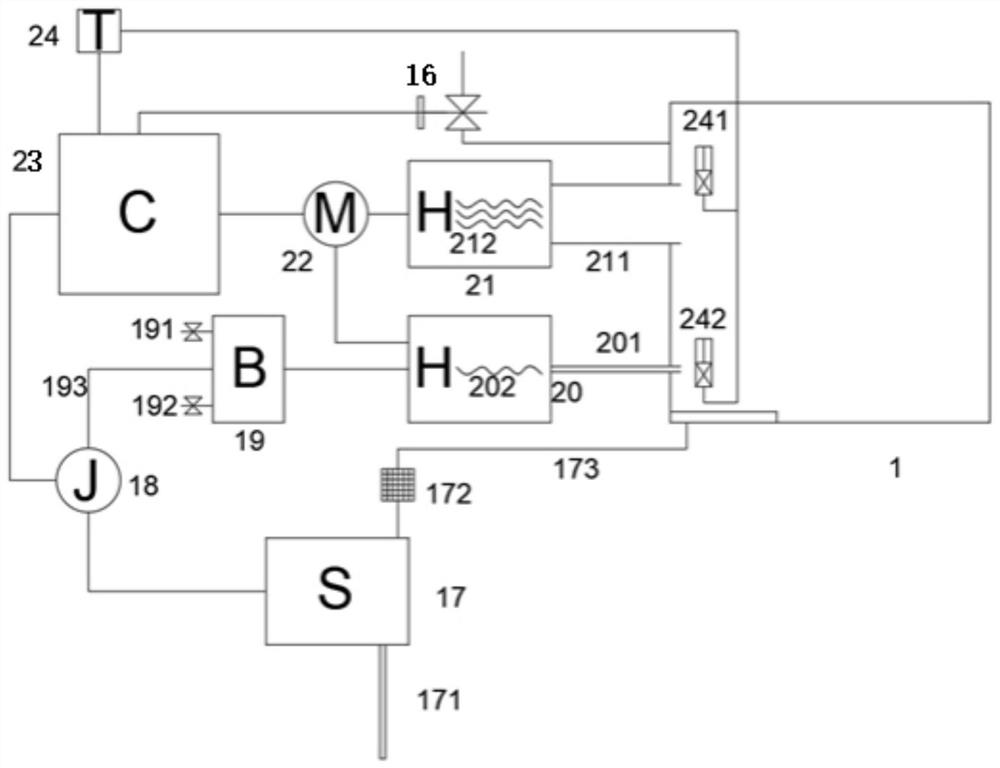
[0074]The high-temperature control unit includes a heater 21, a temperature sensor 241, a temperature-humidity meter 24, and a fan 22; the low-temperature control unit includes a liquid nitrogen inlet and outlet valve 16, a temperature sensor 241, a temperature-humidity meter 24, and a fan 22; Combination, drainage circuit, humidity sensor 242 and temperature and humidity meter 24. The main environmental box 1 has a cubic appearance, including the outer frame of the box, the inner cavity of the box and the switch door 2 of the environmental box. The fixed support box 10 is a floor-standing structure, which is used to fix and support the main environment box 1, and at the same time install the hardware facilities of the electronic control system inside. The electric control system integrates high temperature, low temperature, and humidity signals, and the control instrument panel 7 realizes test environment paramete...


PUM


Abstract

The invention provides a controllable temperature and humidity environment box and a control circuit. The controllable temperature and humidity environment box comprises a main environment box body, a fixed supporting box body, a motor, a high-temperature control unit, a low-temperature control unit, a humidity control unit, a control instrument panel, a temperature and humidity instrument and a fan; one side of the main environment box body is connected with one side of the fixed supporting box body, the motor is installed on the inner wall of the side, close to the main environment box body, of the fixed supporting box body, and the fixed supporting box body is connected with the motor and adjusts the height through the motor; the high-temperature control unit is installed on the inner wall of the side, close to the fixed supporting box body, of the main environment box body, the low-temperature control unit is installed on the side, perpendicular to the fixed supporting box body, of the main environment box body, and the humidity control unit is installed in the fixed supporting box body. High temperature, low temperature and humidity of the main environment box body can be controlled in a high-precision and high-stability manner, the control panel can set program control related parameters, and temperature and humidity are increased and reduced at a certain speed as a cycle test working condition.

Description

technical field [0001] The invention relates to the technical field of detection equipment, in particular to a controllable temperature and humidity environment box and a control circuit. Background technique [0002] The working range of the current temperature and humidity environmental chamber is usually at a certain high temperature and humidity, and the working conditions are single. After setting the target parameters, the environmental chamber works to make the interior of the chamber reach the specified temperature or humidity, and then keep it unchanged. In addition, the commonly used temperature and humidity chamber simply puts the sample into the environmental chamber to verify the resistance of the sample in a specific environment. [0003] Electronic products and related emerging materials work in hot and humid environments, and at the same time bear a variety of mechanical forces, such as friction, stretching, compression, bending, etc. Considering the actual ...

Claims


Application Information

Patent Timeline
IPC IPC(8): G05D27/02
CPCG05D27/02
Inventor 蔡晓静
Owner SHANGHAI JIAO TONG UNIV
Why Eureka
Try Eureka