Dry mill

A mill and dry technology, applied in the field of mining equipment, can solve the problems of inaccurate experimental data, hindering product development, low work efficiency, etc., and achieve the effect of accurate detection data, conducive to product development and high work efficiency

Pending Publication Date: 2020-12-04
郴州市东卓矿山设备有限公司
View PDF0 Cites 0 Cited by
  • Summary
  • Abstract
  • Description
  • Claims
  • Application Information

AI Technical Summary

Problems solved by technology

[0003] Currently used vertical grinding equipment, such as the Chinese patent No. 2019222968906, named vertical grinding machine, although the resistance of the ball medium movement is small and the efficiency of grinding materials is high, but when the grinding materials are viscous In the case of slime or mud, the grinding material and the ball media are bonded into agglomerates, resulting in low work efficiency and high energy consumption
[0004] Secondly, during the movement of the rotating ball medium of the stirring device, the wear between the ball medium, the grinding material and the stirring device is large, resulting in damage to the blades of the stirring device, short service life and high use cost
[0005] Thirdly, when the grinding material of the mill is dry material, the friction between the ball medium, the grinding material and the stirring device causes the high temperature of the grinding material, usually reaching above 180 degrees Celsius, thus changing the properties of the material, resulting in inaccurate experimental data and hindering Product development, inconvenient

Method used


Image

  • Dry mill
  • Dry mill
  • Dry mill

Examples


Embodiment Construction

[0042] The present invention is described in detail below in conjunction with accompanying drawing and specific embodiment:

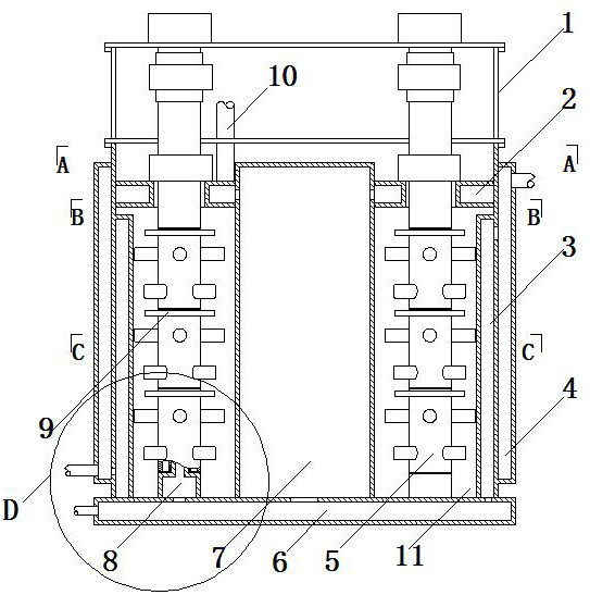
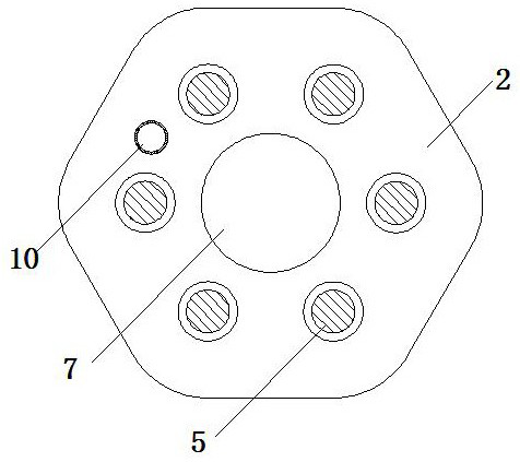
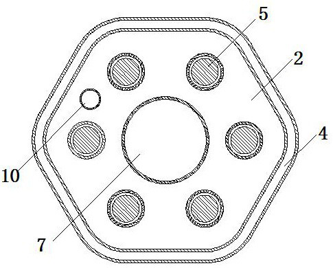
[0043] like figure 1 , figure 2 , image 3 , Figure 4 , Figure 5 , Image 6As shown, the dry mill of the present invention includes a cylinder, an agitator 5 driven by a motor, a support frame 1 for fixing the motor and agitator 5, and a cooling system. There are at least three stirring chambers 11 arranged in a quincunx shape in the barrel. The preferred range of the number of stirring chambers 11 in the cylinder is 3-8. Stirring chamber 11 is provided with feed pipe. The feeding pipe is respectively communicated with the stirring chamber 11 and the feeding device. A partition 12 is provided on the wall of the stirring chamber 11 on one side of the feed pipe, and the partition 12 isolates two adjacent stirring chambers 11 . The top of the cylinder body is closed by a plate and is provided with a discharge port 10, which communicates with th...


PUM


Abstract

The invention discloses a dry mill. The dry mill comprises a cylinder body, stirrers driven by motors, a supporting frame for fixing the motors and the stirrers, and a cooling system, wherein at leastthree stirring cavities which are arranged in a quincunx shape are formed in the cylinder body, the stirring cavities are provided with feeding pipes, and the supporting frame is fixed above the cylinder body; the stirrers extend into the stirring cavities, the stirrers comprise stirring shafts, shaft sleeves and stirring rods, the stirring shafts are hollow shafts, and the shaft sleeves are arranged on the stirring shafts in a sleeving mode and are connected with the stirring shafts in a clamped mode; and the cooling system involves a central water cavity, the central water cavity is formedin the center among the stirring cavities which are arranged in a quincunx shape in the cylinder body and is isolated from the stirring cavities, the bottom of the central water cavity is provided with a water inlet communicating with a water source, and the upper part of the central water cavity is provided with a drainage opening communicating with a drainage pipe. The high temperature of the stirring cavities is effectively controlled, and the property of materials is prevented from being changed due to high temperature, so that material detection data are accurate, product research and development are facilitated, and use is convenient.

Description

technical field [0001] The invention relates to mining equipment, in particular to a dry mill. Background technique [0002] The cylinder of the currently used vertical grinding equipment is equipped with blade-type stirring devices and ball media, such as ceramic balls, glass balls, steel balls, etc. The rotation of the stirring device makes the ball media rotate, thereby producing impact and grinding effects to grind the materials . [0003] Currently used vertical grinding equipment, such as the Chinese patent No. 2019222968906, named vertical grinding machine, although the resistance of the ball medium movement is small and the efficiency of grinding materials is high, but when the grinding materials are viscous In the case of slime or mud, the grinding material and the ball media are bonded into agglomerates, resulting in low work efficiency and high energy consumption. [0004] Secondly, during the movement of the rotating ball medium of the stirring device, the wear...

Claims


Application Information

Patent Timeline
Patent Type & Authority Applications(China)
IPC IPC(8): B02C17/10B02C17/16B02C17/18B02C23/18
CPCB02C17/10B02C17/16B02C17/18B02C23/18
Inventor 李细国
Owner 郴州市东卓矿山设备有限公司
Why Eureka
Try Eureka