
Microphone and its manufacturing method

A manufacturing method and microphone technology, applied in the direction of sensors, electrostatic transducer microphones, electrical components, etc., can solve problems such as the rupture of the diaphragm 102, the impact of the diaphragm on the performance of the device, and the abnormality of the diaphragm 102, so as to reduce the thickness and improve the device Effects on Reliability and Device Yield

Active Publication Date: 2021-10-19
SEMICON MFG ELECTRONICS (SHAOXING) CORP
View PDF11 Cites 0 Cited by
  • Summary
  • Abstract
  • Description
  • Claims
  • Application Information

AI Technical Summary

Problems solved by technology

However, in the manufacturing process of the above-mentioned MEMS microphone, on the one hand, after the back cavity 101a is formed, it is easy to form a sharp corner 100a at the position of the opening of the substrate 100 close to the diaphragm 102, so that the diaphragm 102 is easy to touch when vibrating. The sharp corner 100a will cause the diaphragm 102 to break, the device will fail, and the yield will be lost; on the other hand, if the sacrificial layer 101 is designed to be thin, it will pose a huge challenge to the etching and debugging of the back cavity 101a
[0004] In addition, since the sacrificial layer 101 is tiled on the front surface of the substrate 100, when the process recipe is adjusted, for example, a certain degree of over-etching is performed when etching the substrate 100 to form an opening to eliminate the sharp corner 100a, if The over-etching process causes the sacrificial layer 101 in the area of ​​the back cavity 101a to be etched open, thereby exposing the diaphragm 102, and then when the sacrificial layer 101 in the area of ​​the back cavity 101a is subsequently released through the opening, the diaphragm 102 will be abnormal
Moreover, the abnormality of the diaphragm will affect the performance of the device, and even cause the device to fail.

Method used


Image

  • Microphone and its manufacturing method
  • Microphone and its manufacturing method
  • Microphone and its manufacturing method

Examples


Embodiment Construction

[0025] In the following description, numerous specific details are given in order to provide a more thorough understanding of the present invention. It will be apparent, however, to one skilled in the art that the present invention may be practiced without one or more of these details. In other examples, some technical features known in the art are not described in order to avoid confusion with the present invention. It should be understood that the invention can be embodied in different forms and should not be construed as limited to the embodiments set forth herein. Rather, these embodiments are provided so that this disclosure will be thorough and complete, and will fully convey the scope of the invention to those skilled in the art. In the drawings, the size and relative sizes of layers and regions may be exaggerated for clarity. Like reference numerals refer to like elements throughout. It will be understood that when an element or layer is referred to as being "on" or...


PUM


Abstract

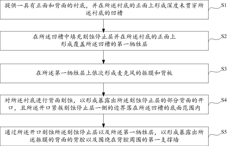
The invention provides a microphone and a manufacturing method thereof. By adding grooves on the front side of the substrate, the thickness of the film layer material used to make the back cavity can be relatively increased, and the back cavity can be etched with a larger debugging space, which is advantageous. It is beneficial to increase the etching time from the direction of adjusting the process formula, thereby improving or eliminating the sharp corners formed on the front side of the substrate after the back cavity etching, and the sharp corners formed on the front side of the substrate after the back cavity etching still cannot pass through When the adjustment of the process formula is completely eliminated, the addition of the groove can increase the distance from the sharp corner on the front of the substrate to the diaphragm, so that the diaphragm cannot touch the sharp corner when vibrating, improving the reliability and good performance of the device. Rate. In addition, the addition of grooves on the front surface of the substrate helps to reduce the thickness of the first sacrificial layer on the periphery of the groove without sacrificing device performance, thereby facilitating the development of the microphone to a smaller size.

Description

technical field [0001] The invention relates to the technical field of semiconductor device manufacturing, in particular to a microphone and a manufacturing method thereof. Background technique [0002] Please refer to figure 1 , the existing manufacturing process of a MEMS (Micro-Electro-Mechanical System, Micro-Electro-Mechanical System) microphone includes: performing etching on the back side of the substrate 100 to open the substrate 100 to form an opening, during which the sacrificial layer 101 is used as The etch stop layer of the substrate 100 needs to have a certain thickness; and then part of the sacrificial layer 101 is etched and removed through the opening to form the back cavity 101a exposing the diaphragm 102, and after the back cavity 101a is formed, a certain amount of sacrificial layer 101 is required to remain The amount is used as a supporting wall for supporting the diaphragm 102. [0003] With the development of technology, MEMS microphones are develop...

Claims


Application Information

Patent Timeline
Patent Type & Authority Patents(China)
IPC IPC(8): H04R19/00H04R19/04H04R31/00
CPCH04R19/005H04R19/04H04R31/00H04R2201/003
Inventor 徐希锐
Owner SEMICON MFG ELECTRONICS (SHAOXING) CORP
Learn More