Cleaning robot

A cleaning robot and cleaning technology, which is applied in the field of cleaning robots to achieve the effects of avoiding leakage, uniform distribution of friction, and avoiding slippage and deviation.

Pending Publication Date: 2021-08-17
POSITEC POWER TOOLS (SUZHOU) CO LTD
View PDF0 Cites 1 Cited by
  • Summary
  • Abstract
  • Description
  • Claims
  • Application Information

AI Technical Summary

Problems solved by technology

Make the contact between the cleaning module and the working surface more uniform, and the grip of the driving wheel is more balanced, avoiding the problem of uneven cleaning caused by deviation

Method used


Image

  • Cleaning robot
  • Cleaning robot
  • Cleaning robot

Examples


Embodiment 1

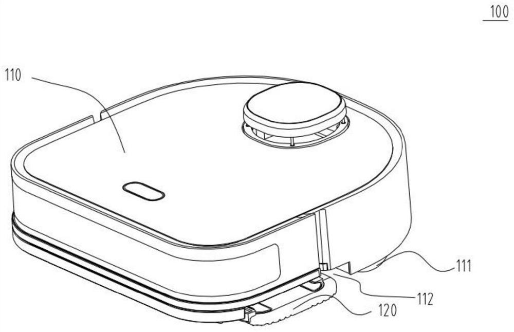
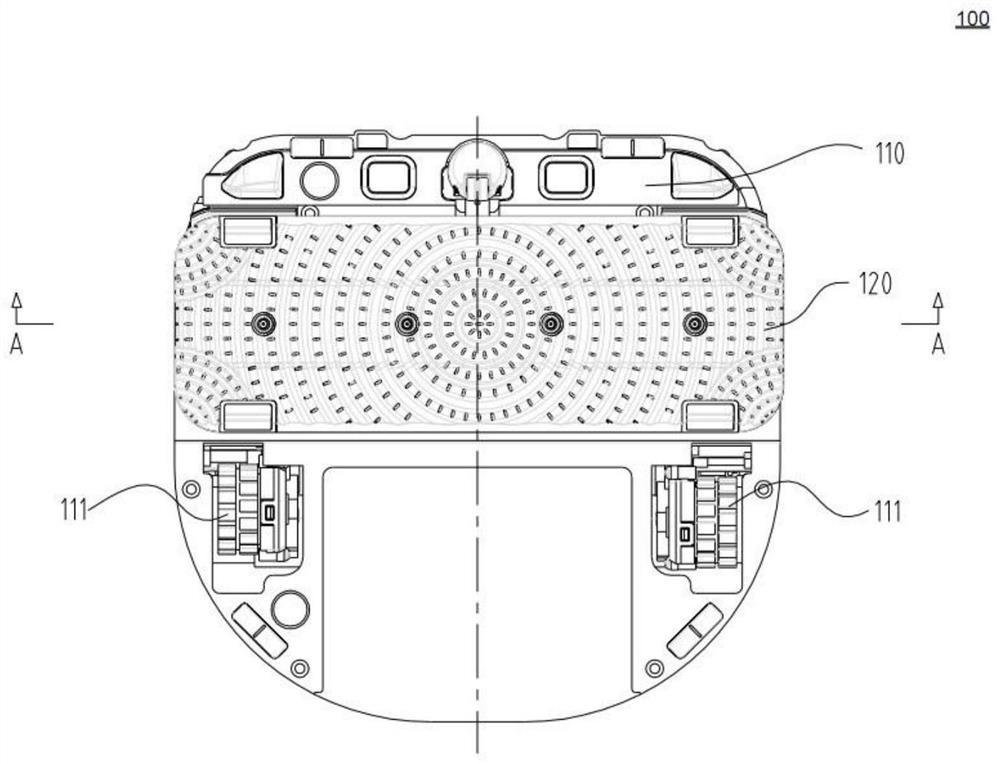
[0049] Such as Figure 1 to Figure 7 It is the first embodiment of the present invention. refer to figure 1 and Figure 5 , the cleaning robot 100 includes a body 110 . The walking module supports the body 110 and drives the cleaning robot 100 to move on the working surface, and includes a driving motor and multiple walking components. In this embodiment, the walking component optionally includes two driving wheels 111 . The control module has an integrated circuit board for connecting and controlling various functional modules, and can control the cleaning robot 100 to walk in a preset working area, and control the cleaning module 120 to perform cleaning tasks. A cavity 112 is provided at the bottom of the fuselage 110 , and the opening direction of the cavity 112 faces the working surface, at least partially accommodating the cleaning module 120 from above the cleaning module 120 . The cleaning module 120 is used to clean the working surface. The cleaning module 120 incl...

Embodiment 2

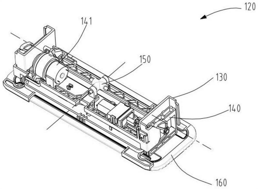
[0056] The difference between the second embodiment and the first embodiment lies in that the structure of the cleaning module 120 and the structure of the pivoting part 150 are different. refer to Figure 8 , the cleaning module 120 includes a mopping floor 160 . The lifting mechanism 140 that is responsible for lifting and mopping the floor is fixedly connected with the bottom of the fuselage 110 to become one. The lifting mechanism includes a lifting motor 141 and a transmission mechanism. The bottom can move up and down relative to the bottom of the fuselage. The lifting mechanism 140 also includes a receiving plate 143 for installing the mopping floor 160 , which is fixedly connected with the bottom of the lifting frame and located at the top of the cavity 112 . The receiving plate 143 drives the mopping floor 160 to move up and down through the transmission mechanism under the drive of the lifting motor 141 of the lifting mechanism 140 . The receiving plate 143 is det...


PUM


Abstract

The invention relates to a cleaning robot. The cleaning robot comprises a robot body; a walking module which supports the robot body and drives the cleaning robot to move on a working surface; a cleaning module which is mounted at the bottom of the machine body and is used for cleaning a working surface; and a control module which controls the walking module to drive the cleaning robot to move, wherein a pivoting part is arranged between the cleaning module and the bottom of the machine body, and the cleaning module can pivot relative to the machine body through the pivoting part; the pivoting part comprises a first pivoting shaft, the first pivoting shaft is approximately parallel to the longitudinal axis of the machine body, and the cleaning module can swing around the first pivoting shaft under the action of external force; and a cavity for containing the cleaning module is formed in the bottom of the machine body, an opening of the cavity faces the working face, and the cleaning module is at least partially contained in the opening direction.

Description

technical field [0001] The invention relates to the field of robots, in particular to cleaning robots. Background technique [0002] With the development of science and technology, intelligent cleaning robots are well known. Not only that, smart sweepers, smart mopping machines and other similar household service robots, with their convenient cleaning, time-saving and labor-saving features, enable people to get rid of tedious housework and enter the family life of ordinary people. [0003] The current smart mopping machines or smart sweeping and dragging all-in-one machines are equipped with a mop to wipe the ground to improve the cleanliness of the ground. Cleaning robots often have one side of the mopping floor in contact with the working surface and the other side does not contact the working surface due to the assembly error of the whole machine or the unevenness of the working surface, which makes the friction distribution between the mopping floor and the working surf...

Claims


Application Information

Patent Timeline
Patent Type & Authority Applications(China)
IPC IPC(8): A47L11/24A47L11/40A47L11/284
CPCA47L11/24A47L11/4061A47L11/4041A47L11/284A47L11/4036A47L11/4005A47L11/4066A47L2201/00A47L2201/04A47L11/40
Inventor 毋宏兵谢明健张士松
Owner POSITEC POWER TOOLS (SUZHOU) CO LTD
Why Eureka
Try Eureka