
Space gridding printing method of 3D printing sand mold

A space grid, 3D printing technology, applied in the direction of mold, core, mold components, etc., can solve the problems of unsatisfactory compaction effect, large amount of binder, easy to appear pores, etc., to shorten the baking time, Reduces gas production and improves breathability

Active Publication Date: 2021-08-17
SHENYANG RES INST OF FOUNDRY
View PDF9 Cites 0 Cited by
  • Summary
  • Abstract
  • Description
  • Claims
  • Application Information

AI Technical Summary

Problems solved by technology

[0004] (1) Since there is no compaction method, the compaction effect is not ideal, and the strength can only be increased by adding a binder. The amount of binder added is large, resulting in The sand mold has a large amount of gas generation;
[0005] (2) 3D printed sand molds have poor air permeability and are prone to defects such as pores and inclusions;
[0006] (3) Large sand molds use a large amount of binder and require a long drying time, resulting in high cost of use
[0007] (4) 3D printing sand molds are added with binders by spraying and infiltration, which cannot achieve the traditional sand mixing effect;
[0008] (5) At present, the particle size of raw sand used in 3D printing sand molds is relatively low, and it is difficult to meet the air permeability requirements of large castings for molding sand

Method used


Image

  • Space gridding printing method of 3D printing sand mold
  • Space gridding printing method of 3D printing sand mold
  • Space gridding printing method of 3D printing sand mold

Examples


Embodiment 1

[0027] The operation process and parameters of the spatial grid printing method of a 3D printing sand mold are as follows:

[0028] The size of the sand mold is 800mm×800mm, the height is 150mm, and the upper part is an arc surface structure of R=500mm, such as figure 1 shown.

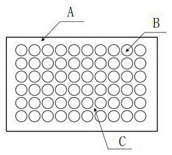
[0029] The first step is to leave a solid wall thickness of 80 mm at the sand mold boundary according to the size of the sand mold, and divide the rest of the space into grids. Use a sphere with a diameter of 6 mm to divide the inner space of the sand mold into each sphere space grid cavity, and each sphere space A gap of 2mm is left between the grid cavities as the support part of the sand mold (see figure 2 ).

[0030] The second step is to import the sand mold 3D entity into the computer of the 3D printing equipment.

[0031] The third step is to use 3D printing to complete the sand mold.

[0032] The fourth step is to bake and heat the sand mold (3 hours at 150°C). After the baking is complet...

Embodiment 2

[0036] The operation process and parameters of the spatial grid printing method of a 3D printing sand mold are as follows:

[0037] The size of the sand mold is 800mm×800mm, the height is 150mm, and the upper part is an arc surface structure of R=500mm, such as figure 1 shown.

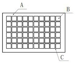
[0038] The first step is to leave a solid wall thickness of 80 mm at the sand mold boundary according to the size of the sand mold, and divide the rest of the space into a grid. Use a cube with a diameter of 6 mm to divide the inner space of the sand mold into each square space grid cavity, and each cube space A gap of 2mm is left between the grid cavities as the support part of the sand mold (see image 3 ).

[0039] The second step is to import the sand mold 3D entity into the computer of the 3D printing equipment.

[0040] The third step is to use 3D printing to complete the sand mold.

[0041] The fourth step is to bake and heat the sand mold (3 hours at 150°C). After the baking is completed, ...

Embodiment 3

[0045] The operation process and parameters of the spatial grid printing method of a 3D printing sand mold are as follows:

[0046] The size of the sand mold is 800mm×800mm, the height is 150mm, and the upper part is an arc surface structure of R=500mm, such as figure 1 shown.

[0047] The first step is to leave a solid wall thickness of 80 mm at the sand mold boundary according to the size of the sand mold, and divide the rest of the space into grids, using a cube grid whose circumscribed ball diameter decreases from 4 mm to 0.2 mm for each layer. Arranged radially from large to small, the internal space of the sand mold is divided into gradient grids of different sizes. (see Figure 4 ).

[0048] The second step is to import the sand mold 3D entity into the computer of the 3D printing equipment.

[0049] The third step is to use 3D printing to complete the sand mold.

[0050] The fourth step is to bake and heat the sand mold (3 hours at 150°C). After the baking is comp...


PUM

PropertyMeasurementUnit
Tensile strengthaaaaaaaaaa
Compressive strengthaaaaaaaaaa
Bending strengthaaaaaaaaaa

Abstract

The invention relates to a space gridding printing method of a 3D printing sand mold. Regarding a single-material casting sand mold for a large casting, when three-dimensional modeling is carried out on the sand mold for casting, an original solid sand mold has a solid wall thickness with enough size and serves as a "facing sand layer" for resisting scouring resulting from molten metal during pouring, and space gridding is carried out on the other parts, so that the original solid state in the sand mold is changed into space gridding which is supported by multiple groups of space frameworks and is internally provided with loose sand not sprayed with a binder. The characteristic of one-time forming of a complex structure is directly achieved through 3D printing. A 3D printing method for the space gridding sand mold is provided. By changing the structure of a gridding area, "a substitute of the back sand layer" is printed out. According to the method, the gas evolution amount of the sand mold is reduced, the air permeability of the sand mold is improved, the interior of the sand mold is gridded, the addition amount of the binder can be reduced, the baking time of the sand mold is shortened, the cost is saved, and the method is applied to the technical field of casting production.

Description

technical field [0001] The invention relates to a spatial grid printing method for 3D printing sand molds in the technical field of casting production. Background technique [0002] At present, the emergence of 3D printing technology has certain advantages in additive manufacturing. At present, the application of 3D technology in the field of sand casting has a very good application prospect. First of all, molding and core making are considered to be one of the links with high labor intensity and harsh production environment in the foundry industry. The production of sand molds using 3D technology replaces manual operations. Due to the particularity of raw materials for 3D printing sand molds, printing There will be no dust in the process, and the binder added to the sand mold hardening is also carried out in a relatively closed box, which reduces environmental emissions and greatly improves the working environment; first, molding and core making are used in the foundry ind...

Claims


Application Information

Patent Timeline
IPC IPC(8): B22C9/02B22C9/12B33Y10/00B33Y40/20
CPCB22C9/02B22C9/12B33Y10/00B33Y40/20Y02P10/25
Inventor 陈瑞李景明熊云龙张海军杜丘赵岭于洋赵黎廷韩智宋蕾宋照伟
Owner SHENYANG RES INST OF FOUNDRY
Features
  • Generate Ideas
  • Intellectual Property
  • Life Sciences
  • Materials
  • Tech Scout
  • Unparalleled Data Quality
  • Higher Quality Content
  • 60% Fewer Hallucinations
Learn More