Eureka AIR delivers breakthrough ideas for toughest innovation challenges, trusted by R&D personnel around the world.

Automatic sand core transfer equipment

A kind of sand core and automatic technology, which is applied in the direction of casting molding equipment, metal processing equipment, mold core, etc., can solve the problems of damage, unsuitable casting, wear and other problems, and achieve the effect of increasing accuracy, increasing stability and increasing production efficiency

Active Publication Date: 2021-08-17
象山联强汽车模具有限公司
View PDF10 Cites 0 Cited by
  • Summary
  • Abstract
  • Description
  • Claims
  • Application Information

AI Technical Summary

Problems solved by technology

[0003] However, the existing sand core transfer equipment has the following defects: the efficiency of manual transfer of sand cores is low, the sand cores are prone to damage during the transfer process, and the installation of sand cores The precision is low, which is not suitable for high-precision product casting. When the sand core volume is large, it is difficult to carry out manual transfer. At this time, it is necessary to use a machine for transfer. Although the transfer efficiency of the machine is high, the transfer of the machine is irregular. When the shape or volume is larger and heavier, the contact part between the clamping device and the sand core is prone to wear and damage due to extrusion and collision, which affects casting efficiency

Method used


Image

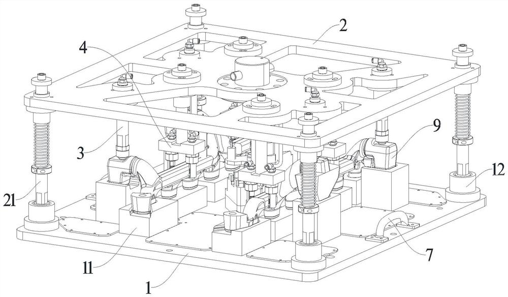
  • Automatic sand core transfer equipment
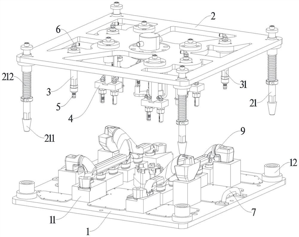
  • Automatic sand core transfer equipment
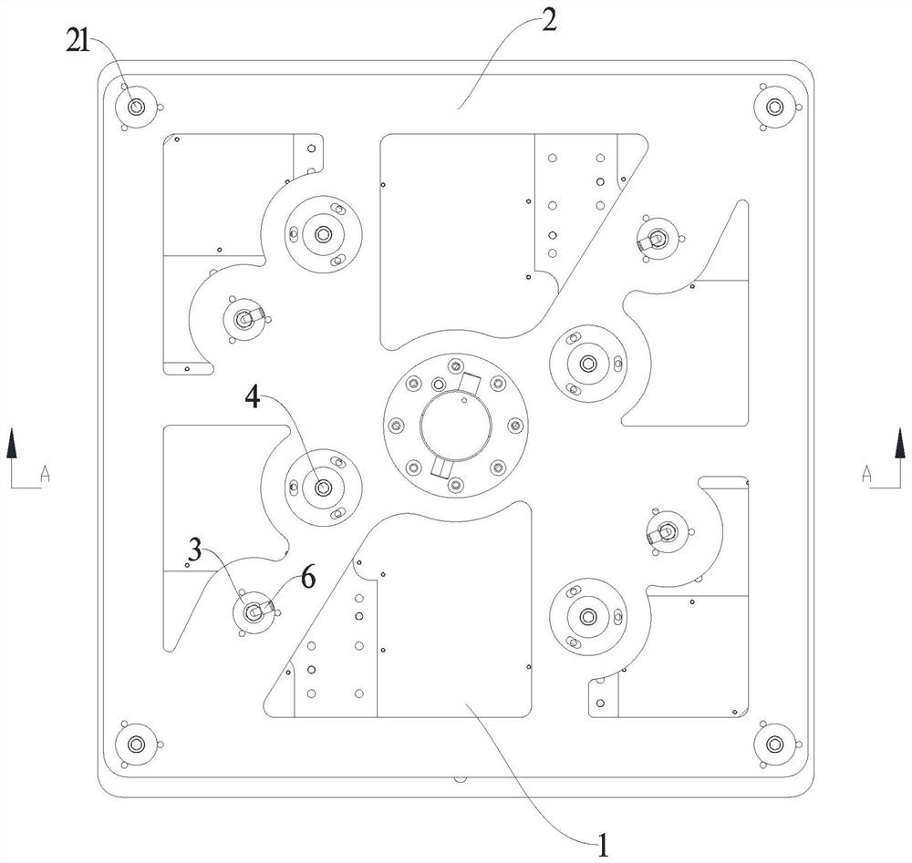
  • Automatic sand core transfer equipment

Examples


Embodiment Construction

[0027] The present application will be further described below with reference to the specific embodiments. It should be noted that, on the premise of no conflict, the embodiments or technical features described below can be arbitrarily combined to form new embodiments.

[0028] In the description of this application, it should be noted that, for orientation words, such as the terms "center", "horizontal", "longitudinal", "length", "width", "thickness", "upper", "lower" , "Front", "Back", "Left", "Right", "Vertical", "Horizontal", "Top", "Bottom", "Inside", "Outside", "Clockwise", "Counterclockwise" ” etc. indicating the orientation and positional relationship are based on the orientation or positional relationship shown in the accompanying drawings, which are only for the convenience of describing the present application and simplifying the description, rather than indicating or implying that the device or element referred to must have a specific orientation or a specific orien...


PUM


Abstract

The invention discloses automatic sand core transfer equipment. The automatic sand core transfer equipment comprises a base, a transfer frame and a manipulator, wherein a mold block for supporting a sand core in a matched mode is arranged on the base; the transfer frame can clamp the sand core on the base; the manipulator is used for carrying the transfer frame; a plurality of inner clamps and outer clamps are arranged on the transfer frame; the inner clamps can stretch into the sand core for clamping; the outer clamps can clamp from the two sides of the sand core; the inner clamps and the outer clamps are each provided with an inflation chuck and an air inlet valve; the inflation chucks and the air inlet valves are arranged in a one-to-one correspondence mode; each inflation chuck comprises an inflation column and an elastic sleeve; the lower end of each inflation column is sleeved with the corresponding elastic sleeve; an air inlet channel is formed in each inflation column; the two ends of each air inlet channel are communicated with the corresponding air inlet valve and the corresponding elastic sleeve respectively; and gas can enter from the air inlet valves and enter the elastic sleeves after passing through the air inlet channels, so that the elastic sleeves expand and clamp the sand core. The transfer efficiency is high, rapid positioning and clamping can be carried out, the stability is high, and the sand core is not prone to being damaged.

Description

technical field [0001] The application relates to the technical field of mold production equipment, in particular to an automatic sand core transfer equipment. Background technique [0002] In the foundry industry, sand cores are usually used in casting. Sand cores are the materials used to make cores in foundry production. They are composed of foundry sand and molding sand binder. The lower core of the sand core is a key process. The quality of handling often determines the quality of the product, and the existing cores are usually transported by man or machine. [0003] However, the existing sand core transfer equipment has the following defects: the manual transfer efficiency of the sand core is low, the sand core is easily damaged during the transfer process, the accuracy of the sand core installation is low, and it is not suitable for high-precision product casting. When the volume of the sand core is large, it is difficult to carry out manual transfer. At this time, i...

Claims


Application Information

Patent Timeline
Patent Type & Authority Applications(China)
IPC IPC(8): B22C23/00B22C9/10
CPCB22C23/00B22C9/10
Inventor 王绍希
Owner 象山联强汽车模具有限公司
Why Eureka
Eureka Blog
Learn More