
A kind of machine tool equipment for the production and grinding of load-bearing cubes

A block and machine tool technology, which is used in grinding machine parts, grinding/polishing equipment, grinding machines, etc., can solve the problems of wasted manpower, large control panel, bumped staff, etc., and achieves convenient locking of workpieces, Manpower saving effect

Active Publication Date: 2022-04-08
南通莱欧电子科技有限公司
View PDF0 Cites 0 Cited by
  • Summary
  • Abstract
  • Description
  • Claims
  • Application Information

AI Technical Summary

Problems solved by technology

[0003] The working conditions of the factory buildings are complex and diverse, so the load-bearing squares of the control panel need to be polished and smoothed, and various installation slots need to be cut on the load-bearing squares of the control panel. The opened installation slots are convenient for loading fixed components. In the past, the control panel required the manual participation of the staff during the grinding process, which was a waste of manpower, and the grinding accuracy was very low, which increased the labor cost, and the volume of the control panel was relatively large, which was easy to hurt the staff

Method used


Image

  • A kind of machine tool equipment for the production and grinding of load-bearing cubes
  • A kind of machine tool equipment for the production and grinding of load-bearing cubes
  • A kind of machine tool equipment for the production and grinding of load-bearing cubes

Examples


Embodiment Construction

[0031] In order to make the object, technical solution and advantages of the present invention clearer, the present invention will be further described in detail below in conjunction with the accompanying drawings and embodiments. It should be understood that the specific embodiments described here are only used to explain the present invention, not to limit the present invention.

[0032] In describing the present invention, it should be understood that the terms "longitudinal", "transverse", "upper", "lower", "front", "rear", "left", "right", "vertical", The orientations or positional relationships indicated by "horizontal", "top", "bottom", "inner", "outer", etc. are based on the orientations or positional relationships shown in the drawings, and are only for the convenience of describing the present invention, rather than indicating or It should not be construed as limiting the invention by implying that a referenced device or element must have a particular orientation, be...


PUM


Abstract

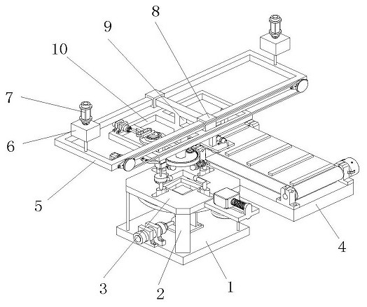
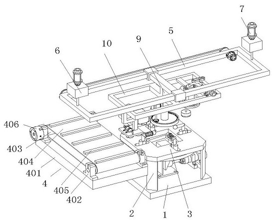
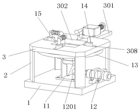
The invention discloses a machine tool for producing and grinding load-bearing blocks, which belongs to the field of grinding devices and includes a load-bearing platform. Four columns are arranged on the top of the load-bearing platform, and the four columns are evenly arranged at four corners of the load-bearing platform. The top of the column is provided with a loading platform, the bottom of the loading platform is provided with a locking turntable, and the locking turntable is connected to the bottom surface of the loading platform in rotation, wherein two extruding blocks are interspersed inside the diverging slots, and the other two The inner side of the diverging wire slot is interspersed with a closing slider, and the extrusion block and the closing slider are respectively slidably connected with the diverging wire slot. A hoisting box is arranged above the loading platform, and a carrying square sleeve is set on the hoisting box. The sleeve is slidably connected to the hoisting frame, and the center of the carrying square sleeve is provided with a drooping frame, and the bottom end of the drooping frame is provided with a load-bearing frame, and one side of the loading platform is also provided with a blanking assembly. When the extruding block and the closing slide block of the present invention move toward the middle at the same time, they will lock the side wall of the bearing block.

Description

technical field [0001] The invention relates to the field of in-air processing, in particular to a machine tool for producing and grinding load-bearing blocks. Background technique [0002] With the development of industrial technology, the development of modern machinery industry is becoming more and more perfect, and a lot of circuits need to be laid in large-scale projects. These circuits need to supply power to the equipment, and the other end of the circuit is connected to the controller. On the panel, because the current working conditions are complex and diverse, and the types of control panels are also diverse, it is necessary to install a load-bearing block on the control panel first, and the control panel can be easily installed on the building through the load-bearing block; [0003] The working conditions of the factory buildings are complex and diverse, so the load-bearing squares of the control panel need to be polished and smoothed, and various installation sl...

Claims


Application Information

Patent Timeline
Patent Type & Authority Patents(China)
IPC IPC(8): B24B27/00B24B41/00B24B41/06B24B47/12
CPCB24B27/0023B24B27/0069B24B41/005B24B41/06B24B47/12
Inventor 许多
Owner 南通莱欧电子科技有限公司
Learn More