High-speed unwinding machine

A pay-off machine, high-speed technology, applied in the direction of conveying filamentous materials, thin material processing, transportation and packaging, etc., can solve the problems of limiting the efficiency of the production line and the low operating speed of the pay-off machine

Pending Publication Date: 2021-08-17
河南省西工机电设备有限公司
View PDF16 Cites 0 Cited by
  • Summary
  • Abstract
  • Description
  • Claims
  • Application Information

AI Technical Summary

Problems solved by technology

At this stage, the operating speed of the pay-off machine is too low, which limits the efficiency of the entire production line to a certain extent

Method used


Image

  • High-speed unwinding machine
  • High-speed unwinding machine
  • High-speed unwinding machine

Examples


Embodiment Construction

[0025] In order to make the purpose, technical solutions and advantages of the present invention clearer, the technical solutions in the present invention will be clearly and completely described below in conjunction with the accompanying drawings. Apparently, the described implementations are part of the implementations of the present invention, not all of them. implementation. Based on the implementation manners in the present invention, all other implementation manners obtained by persons of ordinary skill in the art without creative efforts fall within the protection scope of the present invention. Accordingly, the following detailed description of the embodiments of the invention provided in the accompanying drawings is not intended to limit the scope of the claimed invention, but merely represents selected embodiments of the invention.

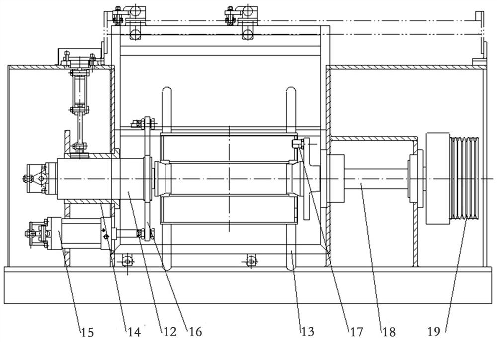
[0026] Such as figure 1 As shown, one end of the jacking cylinder 14 is fixed on the box body 1, the jacking cylinder rod is connected...


PUM


Abstract

The invention discloses a high-speed unwinding machine. The machine comprises a box body, a spool is arranged in the box body, a protective door is arranged outside the box body, one side of the spool is coaxially connected with a sliding sleeve, the sliding sleeve is driven by a jacking air cylinder to tightly jack the spool, the sliding sleeve is sleeved with a sliding sleeve seat, the sliding sleeve seat is fixed to the box body, a main shaft is driven by power on the other side of the spool, a shifting pin inserted into the spool is arranged on the main shaft, and the shifting pin shifts the spool to rotate; and a pneumatic falling preventing mechanism is arranged in the box body and comprises a one-way linear driving mechanism, a connecting rod I and a connecting rod II are hinged to the tail end of the one-way linear driving mechanism, the connecting rod I is hinged to the box body, a brake pad seat is hinged to the tail end of the connecting rod II, a brake pad is fixedly connected to the brake pad seat and located above the sliding sleeve, and the one-way linear driving mechanism drives the brake pad to press the sliding sleeve through the connecting rod II. According to the machine, the automation degree of the high-speed unwinding machine is improved, and potential safety hazards caused by the fact that the spool is not completely locked are eliminated.

Description

technical field [0001] The invention belongs to the field of pay-off devices for metal wires, and in particular relates to a high-speed pay-off machine. Background technique [0002] The pay-off machine is mainly used to take out the semi-finished metal wire wound on the I-shaped wheel and send it to the next process, or to take out the finished wire on the I-shaped wheel for secondary layer winding and packaging. At this stage, the operating speed of the pay-off machine is too low, which limits the efficiency of the entire production line to a certain extent. Considering that the I-shaped wheel will generate a huge moment of inertia when it rotates at high speed, if you want to increase the speed of the original pay-off machine, in addition to increasing the speed of the main shaft, you need to optimize safety and stability. Contents of the invention [0003] The purpose of the present invention is to provide a high-speed wire pay-off machine which improves the line spee...

Claims


Application Information

Patent Timeline
IPC IPC(8): B65H49/32B65H49/30
CPCB65H49/32B65H49/30B65H2701/36
Inventor 朱庆德
Owner 河南省西工机电设备有限公司
Why Eureka
Try Eureka