
Mine rail transportation horizontal sump dredging structure and method

A technology of water tanks and mines, which is applied in the field of mine shaft engineering, can solve the problems of difficult maintenance, time-consuming and labor-consuming, and high maintenance costs in the later period, and achieve the effects of reducing maintenance costs and maintenance time, ensuring personnel safety, and reducing labor costs

Pending Publication Date: 2021-08-17
TONGLING ZHONGDU MINING CONSTR
View PDF1 Cites 0 Cited by
  • Summary
  • Abstract
  • Description
  • Claims
  • Application Information

AI Technical Summary

Problems solved by technology

However, the system requires more machinery and higher setup costs
Moreover, it is difficult to maintain in the later stage, and the maintenance cost is also relatively large, which is time-consuming and labor-intensive, which is not conducive to the rational allocation of resources
[0006] In the prior art, since the mud pump is directly connected to the filling pipe and then discharged to the goaf, there is no filling pipeline for the bottom middle section of the mine, and most of the middle section of the rail does not have a goaf. It is not suitable for the dredging of the bottom rail roadway. At the same time, most of the rail roadways are the largest middle section of the bottom layer of the mine, and the displacement they undertake is several times that of the above middle section. Therefore, the dredging workload is greater, and the use of Ordinary manual dredging requires 10-20 people each time, and the dredging time is 3-7 days (according to the frequency of regular dredging)
The dredging process will occupy the track production roadway and affect mine production

Method used


Image

  • Mine rail transportation horizontal sump dredging structure and method
  • Mine rail transportation horizontal sump dredging structure and method
  • Mine rail transportation horizontal sump dredging structure and method

Examples


Embodiment Construction

[0030] Below in conjunction with accompanying drawing, the present invention will be further described.

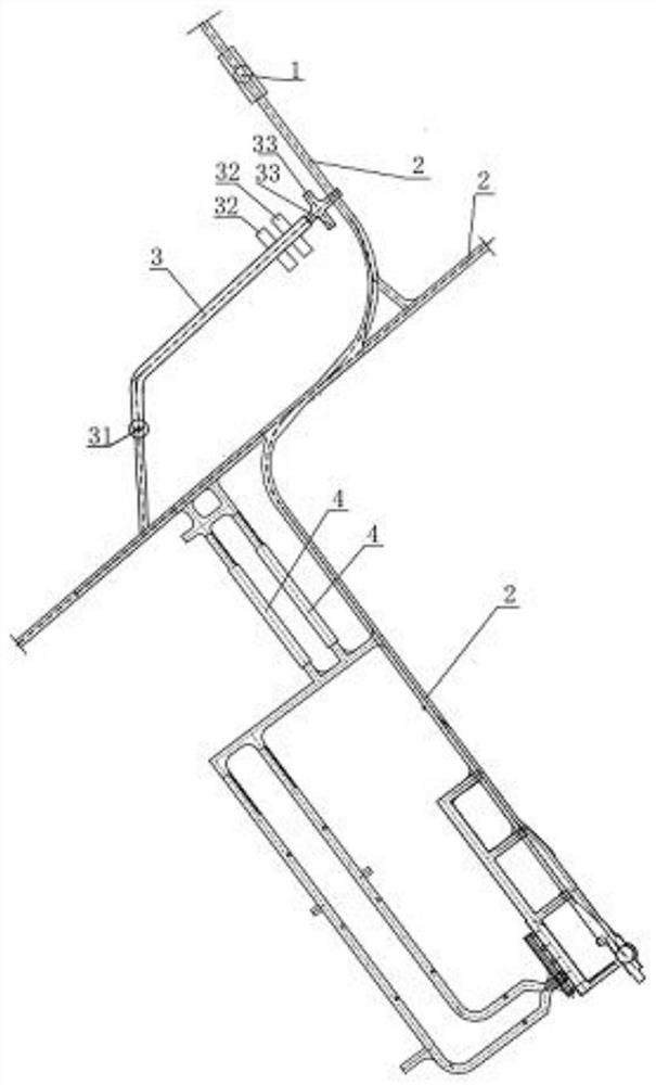
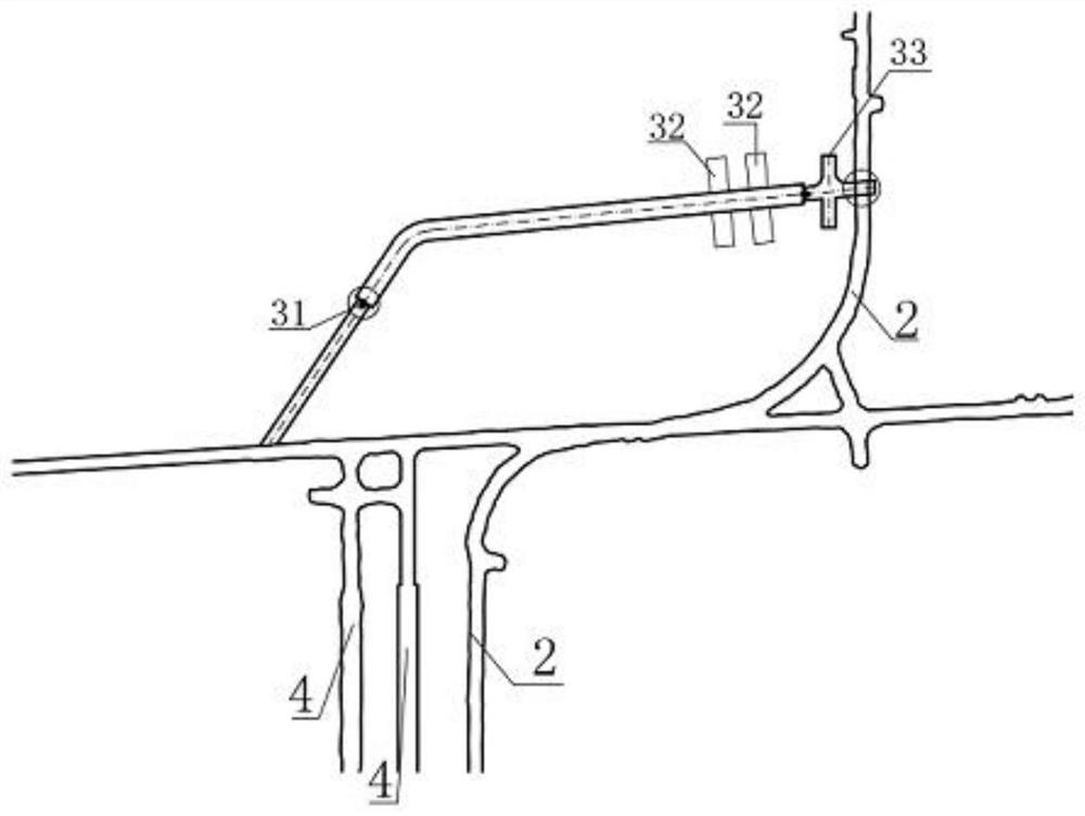
[0031] Such as figure 2 As shown, site selection is carried out in the adjacent track roadway 2, and a dredging chamber 3 with a gentle slope is designed to be excavated. One end of the dredging chamber 3 slope bottom opens near the water tank mouth, and the opening at the other end is Run through the railed roadway 2 so that it overlaps with the railed roadway 2, so that the sludge can be unloaded at the overlapped position with the railed roadway 2.

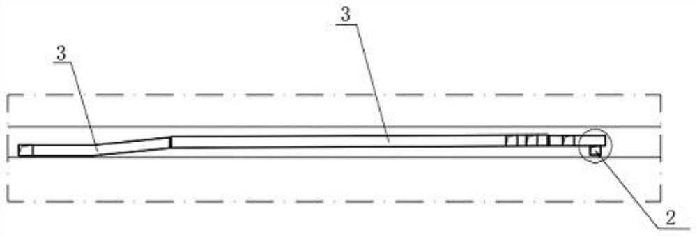
[0032] Such as figure 2 , 3 As shown, the dredging chamber 3 is provided with a water filter wall 31, a silt drain chamber 32 and a forklift turning chamber 33 successively from the place connected to the water tank mouth to the connection prescription with the track roadway, and the water filter wall 31 is used The silt is filtered, blocked in the dredging chamber 3, and the filtered water can be returned to flow into...


PUM


Abstract

The invention discloses a mine rail transportation horizontal sump dredging structure and method. The mine rail transportation horizontal sump dredging structure comprises a dredging chamber, wherein the dredging chamber is arranged between two adjacent rail roadways; a plurality of sludge draining chambers, a forklift turning-around chamber and a water filtering wall are arranged in the dredging chamber; and mud discharging points are arranged in the communicating positions of the dredging chamber and the rail roadways, and the dredging chamber is connected with the rail roadways through mud discharging channels. The mine rail transportation horizontal sump dredging structure has the beneficial effects that the method is flexible and changeable during implementation, a reasonable dredging method can be formulated according to different underground environments, and diversified requirements are met; the cost is greatly reduced during construction and use, and the economic benefits of enterprises can be increased; and the method is safe, is favorable for protecting the personal safety of underground operating personnel and is favorable for implementing the concept of safe operation.

Description

technical field [0001] The invention belongs to the technical field of mine shaft and roadway engineering, and in particular relates to a dredging structure and method for a mine rail transport horizontal water tank. Background technique [0002] In mines, under normal circumstances, two water tanks are set up at each level, which are divided into inner and outer tanks. The sewage gushed out from the excavation and mining face of each level is pumped out by submersible pumps or flows into the site from open ditches and culverts. The horizontal water tank, and the water tank that flows to the next level through the drain well and flows to the lower horizontal water tank through the ditch. Usually, the underground water tank needs to be cleaned regularly, otherwise the mud and silt will lead to the normal operation of the suction well water pump and lead to underground drainage. faults, while the track level is often the maximum production level at the end of the mine, and the...

Claims


Application Information

Patent Timeline
Patent Type & Authority Applications(China)
IPC IPC(8): E21D9/14E21F13/00
CPCE21D9/14E21F13/00
Inventor 陈杰张亚锋王杰荣介鹏张传余朱从宽
Owner TONGLING ZHONGDU MINING CONSTR
Learn More