Brake multi-working-condition reliability test bench

A brake and reliability technology, applied in the field of brake multi-condition reliability test bench, can solve the problems of large space occupation, high energy consumption, low adaptability, etc., and achieves a small space occupation, low energy consumption and light structure Effect

Pending Publication Date: 2021-08-17
CHINA ACADEMY OF RAILWAY SCI CORP LTD +3
View PDF0 Cites 0 Cited by
  • Summary
  • Abstract
  • Description
  • Claims
  • Application Information

AI Technical Summary

Problems solved by technology

[0005] (1) poor versatility
Most of the existing mature test bench products or related inventions are only designed for a single type of brake, or only for a specific installation type of brake, with few mechanical interfaces and low adaptability
[0006] (2) It takes up a lot of space and consumes a lot of energy
At present, some brake fatigue test benches in the industry use a complete wheel to cooperate with the brake test, which leads to a large overall weight of the test bench, a large space occupation, and a lot of energy consumed when driving the wheels.
[0007] (3) The function is not perfect, and it is impossible to truly simulate the various working conditions of the brake in the actual use process
At present, the test bench in the industry basically can only meet the minimum standards of the brake test in the railway industry, and cannot simulate the real working conditions when the brake has different postures such as lateral offset and vertical rotation angle.

Method used


Image

  • Brake multi-working-condition reliability test bench
  • Brake multi-working-condition reliability test bench
  • Brake multi-working-condition reliability test bench

Examples


Embodiment Construction

[0057] In order to have a clearer understanding of the technical features, purposes and effects of the present invention, the specific implementation manners of the present invention will now be described with reference to the accompanying drawings.

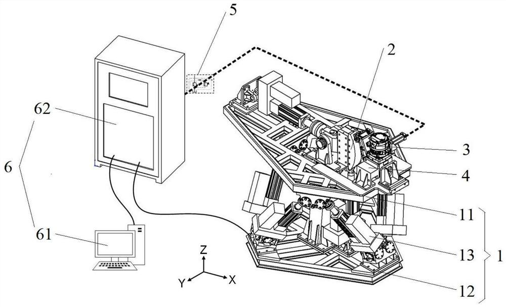
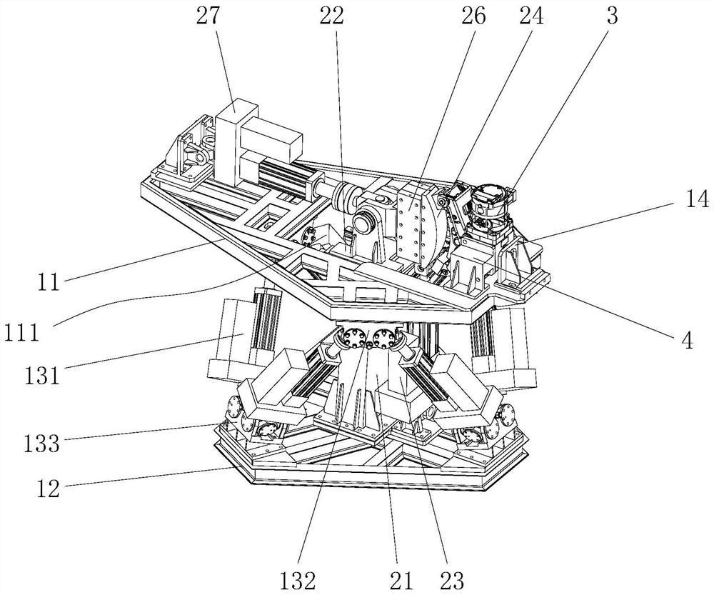
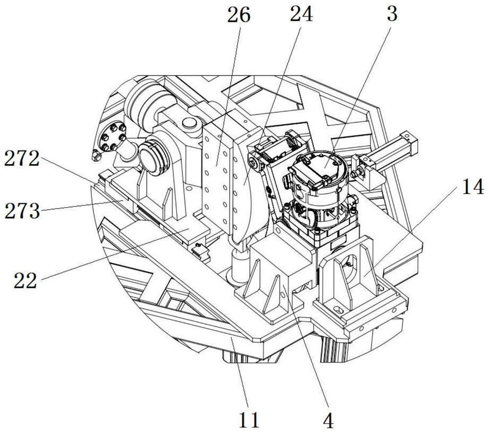
[0058] Such as Figure 1 to Figure 11 As shown, a brake multi-condition reliability test bench is provided in this embodiment, including:

[0059] The posture adjustment platform 1 includes an upper platform 11 and a lower platform 12 arranged at intervals up and down and a first driving mechanism 13 arranged between the upper platform 11 and the lower platform 12. The upper platform 11 has six degrees of freedom, and the first The driving mechanism 13 can drive the movement of the upper platform 11 in six degrees of freedom; the upper platform 11 is provided with multiple sets of mechanical mounting holes for installing the brake; the upper platform 11 is also provided with a through hole 111;

[0060] And the simulated wheel a...


PUM


Abstract

The invention relates to a brake multi-working-condition reliability test bench, which comprises a pose adjusting movable platform and a simulation wheel assembly. The pose adjusting movable platform comprises an upper platform, a lower platform and a first driving mechanism, the upper platform has six degrees of freedom, and the first driving mechanism can drive the upper platform to move on the six degrees of freedom. A plurality of groups of mechanical mounting holes are formed in the upper platform, and a through hole is also formed in the upper platform. The simulation wheel assembly comprises a mounting stand column, a simulation wheel mounting seat, a second driving mechanism and a simulation wheel, the simulation wheel is at least provided with a wheel center of a complete wheel and a partial tread of the complete wheel, the simulation wheel mounting seat penetrates through the through hole and is pivoted with the wheel center of the simulation wheel, and the tread of the simulation wheel can face the brake; the second driving mechanism can pass through the through hole and drive the simulation wheel to swing up and down. The test bench is high in universality, small in occupied space, low in energy consumption, more complete in function and capable of truly simulating various working conditions of the brake in the real using process.

Description

technical field [0001] The invention relates to the technical field of rail transit equipment testing, in particular to a multi-working-condition reliability test bench for brakes. Background technique [0002] With the rapid development of the domestic rail transit field in recent years, the traction capacity and dynamic performance of trains have been increasing day by day, and the requirements for vehicle braking performance have also increased accordingly. In the train braking system, the brake including brake pads, clamps and brake cylinders is the key device when the vehicle produces adhesive braking. It needs to ensure long-term normal operation under relatively complex and harsh conditions under the vehicle, so it is important Extremely high reliability requirements. According to the current railway industry standard "TB / T 3431-2015 Locomotive and Rolling Stock Brake Caliper Unit", before the new brake is put into use, it is necessary to carry out no less than 1 mil...

Claims


Application Information

Patent Timeline
Patent Type & Authority Applications(China)
IPC IPC(8): G01M17/08
CPCG01M17/08
Inventor 常程城赵春光曹伯楠陈骞韩晓辉焦标强李业明张庆爽王正杰李辉吕换小赵彦利郝亮郭斌韩超
Owner CHINA ACADEMY OF RAILWAY SCI CORP LTD
Why Eureka
Try Eureka