Sawtooth diaphragm and its application and its debugging method for optical path

A sawtooth and diaphragm technology, applied in the field of optics, can solve the problems of difficult to observe the dividing point, small repetition frequency laser, low debugging efficiency, etc., and achieve the effect of easy observation and measurement and optical path adjustment, saving time, and high debugging efficiency.

Active Publication Date: 2022-02-22
LASER FUSION RES CENT CHINA ACAD OF ENG PHYSICS
View PDF23 Cites 0 Cited by
  • Summary
  • Abstract
  • Description
  • Claims
  • Application Information

AI Technical Summary

Problems solved by technology

Due to the super-Gaussian distribution of the edge of the infrared laser beam and the small repetition frequency laser energy, it is difficult to observe and judge the exact dividing point of the beam during actual operation, resulting in the need for repeated adjustments and checks, which is time-consuming and laborious
In addition, this method verifies the light adjustment effect of the beam through the development of the official launch site drawings, which is costly, and the laser device needs to be cooled for more than 3 hours after each official launch (Wonterghem, B.M.V., et al., Operations on the National Ignition Facility.FUSION SCIENCE ANDTECHNOLOGY, 2016.69:p.452-469), it will take more than 1 day to develop the official launch site drawings several times, and the debugging efficiency is low

Method used


Image

  • Sawtooth diaphragm and its application and its debugging method for optical path
  • Sawtooth diaphragm and its application and its debugging method for optical path
  • Sawtooth diaphragm and its application and its debugging method for optical path

Examples


Embodiment 1

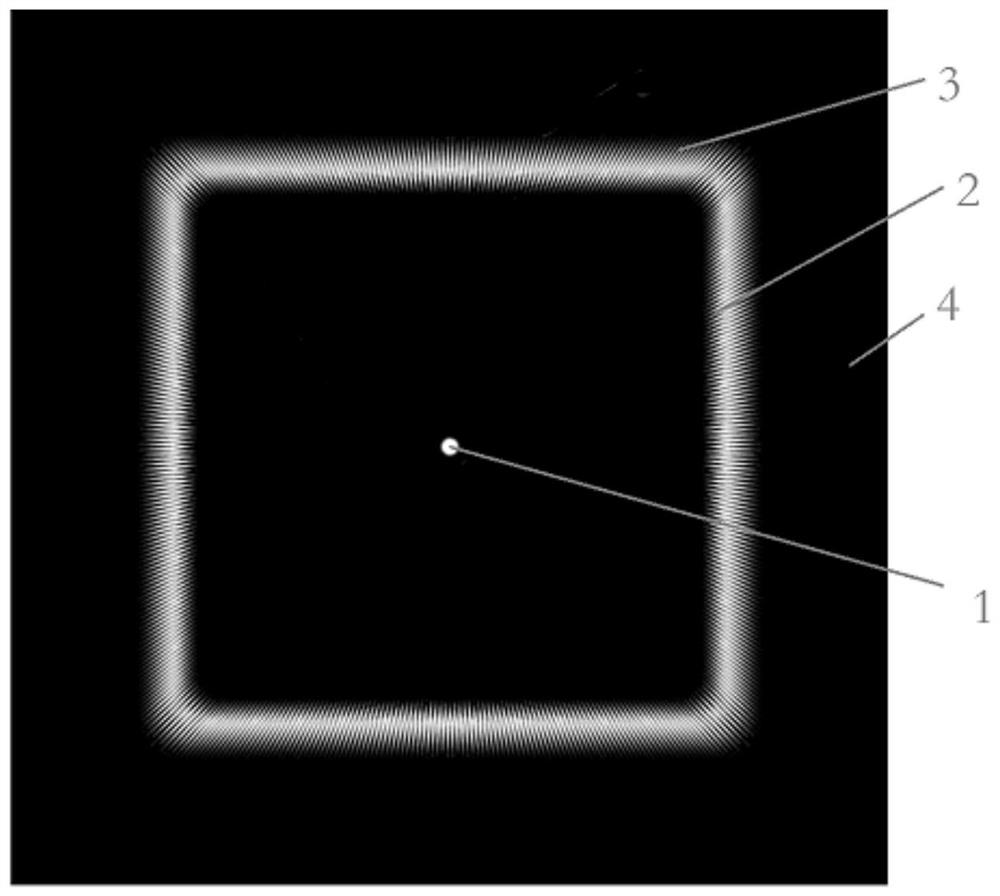
[0044] Such as figure 1 and figure 2 As shown, a sawtooth diaphragm has a circular sawtooth structure 1, a first circular sawtooth structure 2 and a second circular sawtooth structure 3 sequentially etched on the optical plane from the inside to the outside, and the circular sawtooth structure 1 is located at the center of the optical plane. center, and the first annular sawtooth structure 2 and the second annular sawtooth structure 3 take the center of the optical plane as the center, the surrounding area of ​​the circular sawtooth structure 1, the first annular sawtooth structure 2 and the second annular sawtooth structure 3 The surrounding areas of are all light-transmitting areas, and all areas in the optical plane except the light-transmitting areas are light-opaque areas 4 . Preferably, the light-transmitting area is coated with an anti-reflection film to improve the light-transmitting effect, and the opaque area 4 is coated with a gold film to increase the laser damag...

Embodiment 2

[0056] The same part of this embodiment and Embodiment 1 will not be described again, the difference is:

[0057] Such as Figure 1 to Figure 3 As shown, the circumference of the circular sawtooth structure 1 is 26 times the width of the sawtooth, and the overall magnification of the laser device is 8.48 times. Processing technology, the diameter of the circular sawtooth structure 1 is 1.6 mm.

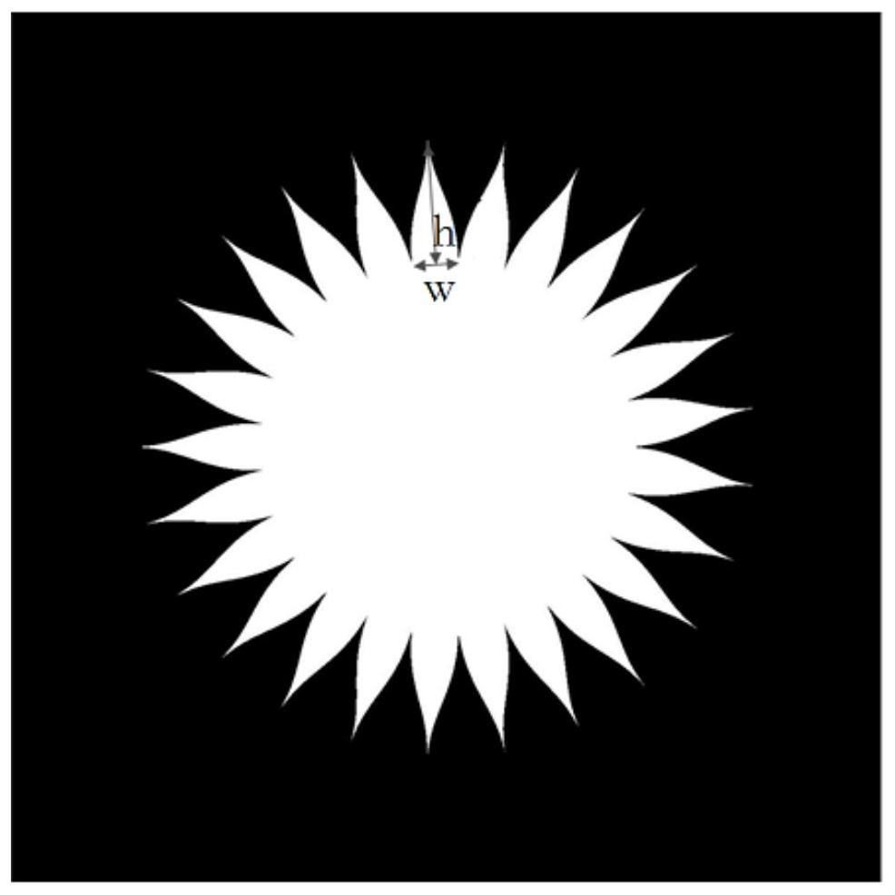
[0058] The first annular sawtooth structure 2, the second annular sawtooth structure 3, and the standard aperture 7 are all 12-order super-Gaussian distributions, and the softening factor is about 7.3%. The side length of the second annular sawtooth structure 3 and the standard aperture 7 is 48mm, and the side length of the first annular sawtooth structure 2 is 43mm. In order to make the convolution effect in the y direction significantly smaller than that in the x direction, the sawtooth width w of the circular sawtooth structure 1 , the first circular sawtooth structure 2 , and the...


PUM


Abstract

The invention relates to a sawtooth diaphragm and its application and a debugging method for an optical path, belonging to the field of optical technology. The optical plane of the sawtooth diaphragm is sequentially etched with a circular sawtooth structure, a first annular sawtooth structure and a second annular sawtooth. structure, the present invention uses a circular sawtooth structure to represent the far-field position of the laser beam, uses the first and second ring-shaped sawtooth structures to represent the edge position of the near-field of the laser beam, and forms a clear and bright edge ring in the near-field of the laser beam. The bright image has obvious contrast with the opaque area, which is convenient for observation and measurement and optical path adjustment. At the same time, it does not need to be developed and checked repeatedly for formal reflection field drawings, saving time, high debugging efficiency, and simple and convenient.

Description

technical field [0001] The invention belongs to the technical field of optics, and in particular relates to a sawtooth diaphragm and its application and a debugging method for an optical path. Background technique [0002] Large-aperture and high-power laser devices can create unprecedented extreme physical conditions such as strong electric fields, strong magnetic fields, and high pressures in the laboratory environment. substitute role. With the continuous progress of precision physical experiments, higher energy and higher power requirements are put forward for large-aperture high-power devices. For this reason, more large-aperture optical components need to be installed. For example, the US National Ignition Device needs to complete 7348 optical components. Installation and debugging (Baisden, P.A., et al., Large Optics for the National Ignition Facility. FUSION SCIENCE AND TECHNOLOGY, 2016.69: p.295-351). The production, processing, and testing processes of large-aper...

Claims


Application Information

Patent Timeline
Patent Type & Authority Patents(China)
IPC IPC(8): G02B5/00G02B7/00
CPCG02B5/005G02B7/00
Inventor 李森宗兆玉赵军普梁樾熊迁龙蛟柴向旭薛峤张晓璐吴振海张君陈波郑奎兴郑万国
Owner LASER FUSION RES CENT CHINA ACAD OF ENG PHYSICS
Why Eureka
Try Eureka