Monitoring device, network system, topology management device and monitoring program
What is AI technical title?
AI technical title is built by Patsnap AI team. It summarizes the technical point description of the patent document.
A monitoring device and network system technology, applied in the field of monitoring programs, can solve the problem of no topology detection and the like
Active Publication Date: 2021-08-17
MITSUBISHI ELECTRIC CORP
View PDF21 Cites 0 Cited by
Summary
Abstract
Description
Claims
Application Information
AI Technical Summary
This helps you quickly interpret patents by identifying the three key elements:
Problems solved by technology
Method used
Benefits of technology
Problems solved by technology
There is no provision for topology detection function in the ERP protocol
Method used
Image
Click on the blue label to locate the original text in one second.
Reading with bidirectional positioning of images and text.
Examples
Embodiment approach 1
[0041] use Figure 1 to Figure 12 This embodiment will be described.
[0042] ***Description of structure***
[0043] >>
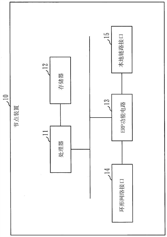
[0044] refer to figure 1 and figure 2 , the configuration of the node device 10 according to this embodiment will be described.
[0045] The node device 10 is a computer.
[0046] Such as figure 1 As shown, the node device 10 has a processor 11 and other hardware such as a memory 12 , an ERP function circuit 13 , a ring network interface 14 and a local link interface 15 . The processor 11 is connected to other hardware via signal lines, and controls these other hardware.
[0233] In this embodiment, differences from the above-described embodiment will be described.
[0234] In this embodiment, the structure of the monitoring device 40 is different from the above-mentioned embodiment.
[0235] >>
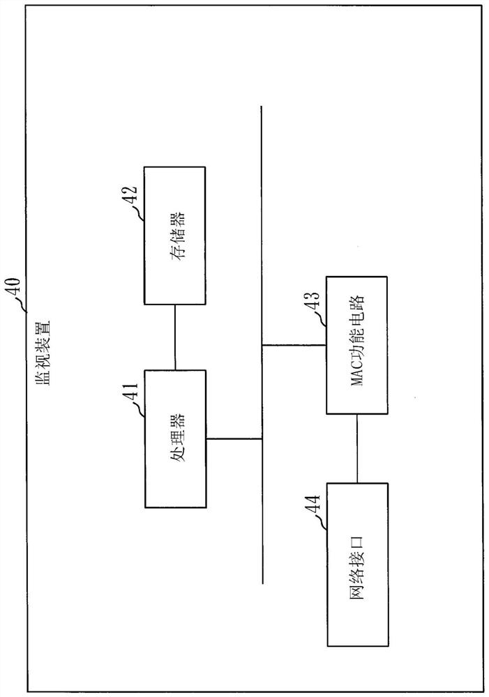
[0236] Figure 15 It is a block diagram of the monitoring device 40 of this embodiment.
[0237] The monitoring device 40 holds the topology definition information 59 in memory in advance.
[0238] The topology definition information 59 is information that defines a connection relationship between nodes in the ring network and information on inter-network nodes that connect the ring networks to each other.
[0239] >
[0240] The monitoring device 40 has a table generation unit 25 .
[0241] The table generating unit 25 of the monitoring device 40 has a function of generating the topology map table 32 . The topology map table 32 is a table in which information of ERP nodes connected to the ring network recognized by the node device 10 is recorded...
PUM
Abstract
According to the present invention, an information acquisition unit (53) of this monitoring device (40) acquires, from each node, adjacent connection information (33) constructed in each node by means of information exchange and information sharing among nodes, and stores the acquired information in a connection information file (38). The adjacent connection information (33) is information indicating connection relationships among nodes. A topology comparison unit (54) of the monitoring device (40) compares connection information included in the adjacent connection information (33) and topology definition information (59) held in advance in a topology definition file (58), and determines whether a ring network configuration is as designed. The topology definition information (59) is information defining the connection relationships among the nodes in the ring network.
Description
technical field [0001] The invention relates to a monitoring device, a network system, a topology management method and a monitoring program. Background technique [0002] Protocols used in ring networks include RPR and ERP, which multiplex user frames on the ring network and distribute them to terminals connected to the network, and switch paths within 50 ms when a network failure occurs. "RPR" is the abbreviation of ResilientProtection Ring (elastic protection ring). "ERP" is an abbreviation of Ethernet (registered trademark) Ring Protection (EthernetRing Protection). RPR has been standardized with IEEE 802.17, and ERP has been standardized with ITU-TG.8023. The RPR protocol has a topology detection function based on Topology Discovery (Topology Discovery), so nodes can perform topology detection within a ring, but there is no regulation related to topology detection when a multi-ring network is formed. There is no provision for the topology detection function in the E...
Claims
Application Information
Patent Timeline
Application Date:The date an application was filed.
Publication Date:The date a patent or application was officially published.
First Publication Date:The earliest publication date of a patent with the same application number.
Issue Date:Publication date of the patent grant document.
PCT Entry Date:The Entry date of PCT National Phase.
Estimated Expiry Date:The statutory expiry date of a patent right according to the Patent Law, and it is the longest term of protection that the patent right can achieve without the termination of the patent right due to other reasons(Term extension factor has been taken into account ).
Invalid Date:Actual expiry date is based on effective date or publication date of legal transaction data of invalid patent.

