
Cigarette filter tip feeding mechanism

A filter tip and cigarette technology, which is applied in the fields of tobacco, cigarette manufacturing, and application, can solve problems such as low conveying efficiency, clogging of cigarette filter tips, clogging of conveying equipment, etc.

Active Publication Date: 2021-08-20
SUZHOU DINNAR TECH FOR AUTOMATION CO LTD
View PDF10 Cites 1 Cited by
  • Summary
  • Abstract
  • Description
  • Claims
  • Application Information

AI Technical Summary

Problems solved by technology

[0004] During the feeding process, the cigarette filter rods are transported to the cigarette production equipment through a pipeline with a length of tens of meters; during the transportation process, the cigarette filter rods are often blocked in the pipeline or on the conveying equipment. , resulting in low conveying efficiency; and this conveying method is a continuous feeding process, which is not convenient for subsequent intermittent processing of filter rods

Method used


Image

  • Cigarette filter tip feeding mechanism
  • Cigarette filter tip feeding mechanism
  • Cigarette filter tip feeding mechanism

Examples


Embodiment 1

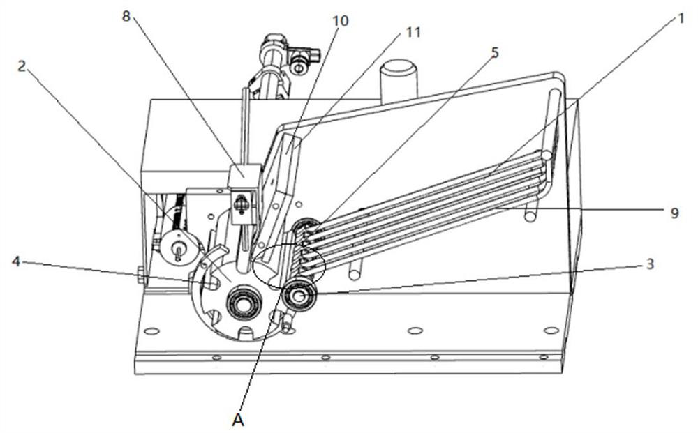
[0033] Please refer to figure 1 , 2 and 3, a cigarette filter feeding mechanism, comprising, a feeding module, which includes a feeding ramp 1 arranged obliquely, used for feeding cigarette filters;

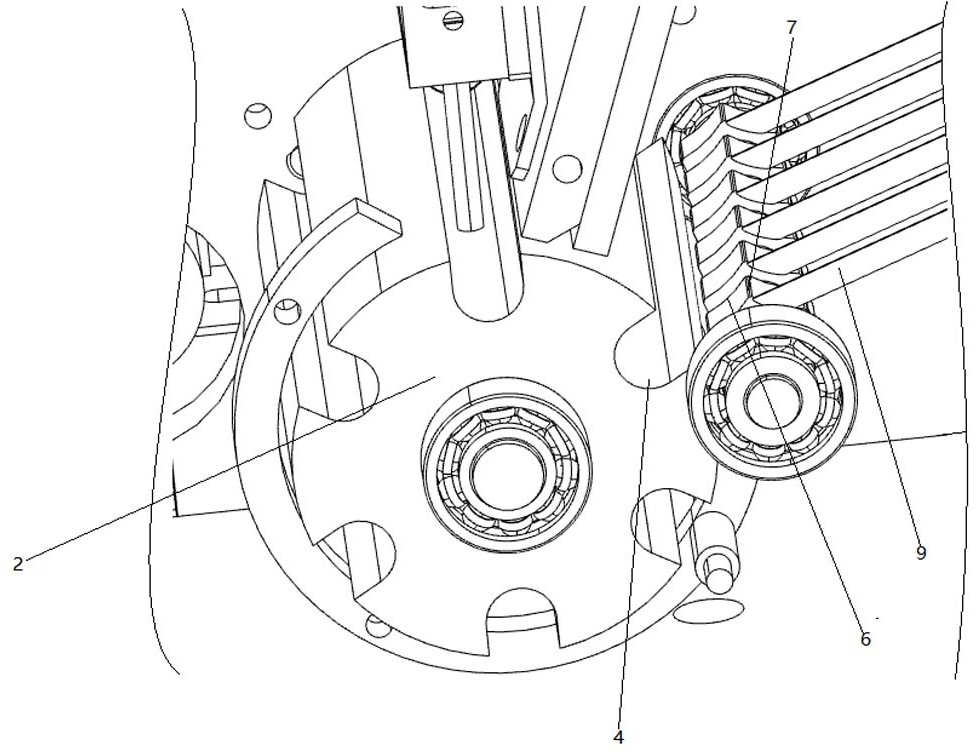
[0034] The feeding roller 2, the circumference of the feeding roller 2 is provided with several U-shaped grooves 4; the U-shaped grooves 4 are used for the transportation of cigarette filters;

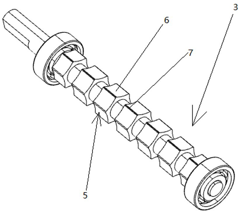
[0035] The auxiliary material roller 3 is located between the upper material roller 2 and the unloading module, and is connected with the bottom of the unloading module; There are several arc-shaped grooves 6 in the circumferential direction; the auxiliary wheel 5 is used to prevent the cigarette filter from being stuck out of the feeding roller 2;

[0036] A driving mechanism, used to drive the feeding roller 2 and the auxiliary feeding roller 3 to rotate intermittently;

[0037] The photoelectric detection device 8 is arranged above the feeding roller 2 and is used to detect whether ...

Embodiment 2

[0046] The following introduces the use steps of the cigarette filter feeding mechanism in this embodiment, including the following steps:

[0047] (1) The cigarette filter tip is rolled from the top of the feeding ramp 1 to the bottom, and deposited along the feeding ramp 1 or at the bottom of the feeding ramp 1;

[0048] (2) The feeding roller 2 and the auxiliary material roller 3 rotate synchronously, and the auxiliary material roller 3 drives the deposited cigarette filter into the U-shaped groove 4;

[0049] (3) The scraper 11 scrapes off excess cigarette filters, and the guide plate 10 guides the cigarette filters stuck between the scraper 11 and the material roller into the U-shaped groove 4;

[0050] (4) The U-shaped groove 4 drives the cigarette filter tip to move counterclockwise. When the feeding roller 2 drives the U-shaped groove 4 equipped with the cigarette filter tip to move to the lower left, under the action of gravity, the cigarette filter tip realizes self-...


PUM


Abstract

The invention discloses a cigarette filter tip feeding mechanism which comprises a discharging module which comprises a discharging ramp arranged in an inclined mode and is used for discharging cigarette filter tips; a plurality of U-shaped grooves which are formed in the circumferential direction of the feeding roller, and the diameter width of each U-shaped groove is larger than that of a cigarette filter tip; a U-shaped groove which is used for transporting cigarette filter tips; an auxiliary material roller which is located between the feeding roller and the discharging module and connected with the bottom end of the discharging module, wherein the auxiliary material roller is sleeved with a plurality of auxiliary wheels, and a plurality of arc-shaped grooves are formed in the auxiliary wheels in the circumferential direction; a driving mechanism which is used for driving the feeding roller and the auxiliary material roller to intermittently rotate; an auxiliary material roller is additionally arranged, and an arc-shaped groove is formed in the auxiliary material roller; an inclined plane can be formed by the arc-shaped groove and the inner wall of the U-shaped groove, so that cigarette butts can be better fed; a stacking angle is further formed between the adjacent arc-shaped grooves and the discharging module, when the auxiliary material roller rotates, the cigarette butts can be better driven, and deposition and blockage are avoided.

Description

technical field [0001] The invention relates to the technical field of cigarette production equipment, in particular to a cigarette filter tip feeding mechanism. Background technique [0002] The content of harmful substances in cigarette smoke is an important indicator to measure the quality of cigarettes and their impact on human health. Harmful substances in cigarettes are produced in the process of dry distillation and thermal cracking when cigarettes are burned. Combustion conditions are related to many factors such as time, amount of combustion material, filter conditions, and flue gas dilution ratio. At present, there are two ways to reduce harmful substances in cigarette smoke. One is to reduce the content of harmful substances in cigarettes, mostly to reduce the production of harmful substances in cigarettes. Accelerator, changing the specifications of cigarettes, reducing the amount of shredded tobacco, reducing the number of cigarette puffs, etc.; the second is t...

Claims


Application Information

Patent Timeline
Patent Type & Authority Applications(China)
IPC IPC(8): A24C5/47
CPCA24C5/478
Inventor 秦应化顾正林
Owner SUZHOU DINNAR TECH FOR AUTOMATION CO LTD
Learn More